ThinkPad Pen Tablets

ThinkPad 710T

Machine Type 2523 · 1993 · 33 sections

IBM's keyboardless pen tablet: a 486SLC2 slate with a 640×480 16-grey pen screen, 4–12 MB of memory and either a 60 MB hard disk or ThinkPad File (TPF) flash cards.

This transcribed historical service reference may contain incomplete captures. The linked original manuals remain authoritative.

Service Reference

Product Overview #

Compiled from a hardware survey and IBM's product records. A dash means no source records the value.

ThinkPad 710T specifications
Specification ThinkPad 710T
Released March 1993
Processor IBM 486SLC, 25 MHz (soldered QFP package)
Chipset Western Digital WD76C10A
Bus AT bus
Memory Standard 4 MB soldered; maximum 12 MB; 1 × 72-pin SIMM slot
Storage 2.5" IDE or solid-state PCMCIA: 60 MB HDD or 5, 10 or 15 MB SSD; adapter cable required
Display 9.5" backlit transflective passive matrix greyscale (16 shades), 640 × 480
Graphics Western Digital WD90C26
Audio PC speaker
Main battery NiCad
CMOS battery Socketed lithium coin cell
Media drives None; external floppy drive supported
PC Card slots 1 × PCMCIA Type II (hard disk models) or 3 × Type II (solid-state models)
Networking Modem (optional)
Ports
  • Parallel
  • Serial
  • VGA out
  • 2 × PS/2
  • External floppy connector
BIOS IBM BIOS
Pointing device Pen (digitiser)

General Checkout #

Source: Hardware Maintenance Manual Volume 1: Laptop, Notebook, Portable and ThinkPad Computers, p.298

Start here when the 710T does not start or work correctly. Work through the numbered steps in order and, where a step asks a question, follow its Yes or No branch.

The diagnostic tests are intended to test only IBM products. Non-IBM products or modified options can give false errors and invalid responses.

001
  • Power-off the computer and all external devices.
  • Check that all the cables and the power cord are properly connected.
  • Power-on the computer while holding the Suspend/Resume switch in the On position. Check for the following responses:
    • The power on indicator lights. The Suspend/Resume indicator works as the power on indicator when the power switch is pressed.
    • One long beep sounds.
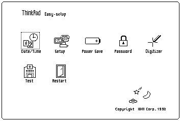
    • Memory test begins (memory size appears on the top-left corner of the screen) and the Easy-Setup screen or Password Menu screen appears.

    Note: If the Resume/Suspend Switch is not held in the On position when the computer is powered-on, the user defined screen appears.

Did either the Easy-Setup or Password Menu screen appear?

Easy-Setup screen with icons for Date/Time, Setup, Power Save, Password, Digitizer, Test and Restart

Yes — go to Step 003. No — go to Step 002.

002

Go to Step 004.

003
  • Enter the password on Password Menu screen, if it appeared.
  • Select Test on the Easy-Setup screen and go to Step 007.
004

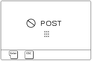
Did the following screen appear?

POST error screen: a prohibition symbol, the word POST and the error codes (xxx), with Enter and Esc buttons below

Yes — go to Step 006. No — go to Step 005.

005
006
007

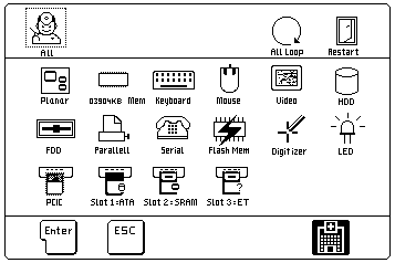
Did the Test Menu appear?

Test menu with All, All Loop and Restart icons above icons for each device to test: planar, memory, keyboard, mouse, video, HDD, FDD, parallel, serial, flash memory, digitizer, LED, PCIC and slots 1 to 3

Yes — go to Step 009. No — go to Step 008.

008
009

Is the displayed configuration correct with the installed devices?

Note: Installed devices are displayed in a dark shade, devices not installed are displayed in a gray shade.

Yes — go to Step 011. No — go to Step 010.

011
  • Select All on the Test Menu and go to Step 012. (Diagnostic test will run on all devices displayed in a dark shade.)
012

Did the tests find a device error?

A device error is displayed with an X over the device. The device ID (XXX), an error description code (YY), and FRU code (ZZZZ) are displayed.

For example:

Example of a device error on the test menu: the device icon is crossed out with an X, with the codes XXX YY ZZZZ shown above it

XXX
Device ID
YY
Error Description Code
ZZZZ
FRU Code

Note: If the test stops or hangs when the test is running, replace the last device that was tested.

Yes — go to Step 014. No — go to Step 013.

013

The error was not detected by the test:

  • Check that the cables and connectors are not damaged.
  • Reconnect all adapters, drives, and modules, then test the computer several times. An All Loop option is available for looping all the tests. To exit from the looping, select the test icon on the right, bottom corner of the screen at the time of between each test.
  • If no error is detected, go to Symptom-to-FRU Index and use the user reported symptom.
  • If any errors are detected, go to FRU Codes.
014
  • Note the error codes shown on the screen and go to FRU Codes and replace the appropriate FRU.

Memory Checkout #

Source: Hardware Maintenance Manual Volume 1: Laptop, Notebook, Portable and ThinkPad Computers, p.302

Note: Before removing a SIMM card, power-off the computer.

Error code 110 indicates that a parity check error on the system board was detected. The error is caused by the SIMM card or the system board.

To isolate the FRUs, remove the SIMM card and run the memory test again.

  • If an error occurs without the SIMM card, replace the system board.
  • Otherwise, replace the SIMM card.

Note: The system board contains the first 4MB of the memory.

Checking the Installed Devices List #

Source: Hardware Maintenance Manual Volume 1: Laptop, Notebook, Portable and ThinkPad Computers, p.314

If a device is installed but the icon appears in gray shade rather than dark shade on the Test Menu, it means that the device is defective. Make sure that the device is connected properly. If the symptom continues, replace the device or the system board.

FDD, Parallel, and Serial icons are always displayed in dark shade. That is, these icons represent adapters on the system board and do not represent external devices.

Short Circuit Test #

  1. Visually check the cables, wires, and connecters for any short circuits, open wires, and damage. If a short circuit or burned parts are found, replace the parts.
  2. Disconnect, then reconnect all the external devices from the computer one by one and see if the same symptom appears. If you find that an external device has a problem, follow the maintenance procedure for that device.
  3. If the same symptom remains with no external devices connected, the problem is in the computer. Isolate the failing component in the computer by changing the FRUs one by one until you find the problem. Replace the DC/DC card and the system board first.

    If the symptom is that the battery becomes low on power quickly, and all the tests run without detecting any errors, replace the battery pack first.

AC Adapter Test #

  1. Unplug the AC adapter from the power outlet and the computer.
  2. Inspect the AC adapter for any signs of overheating or damage.
  3. Inspect the AC adapter power cord for cuts or damage. Replace the power cord, if necessary.
  4. Plug the power cord into a power outlet. Listen for any sound that might indicate defective operation.
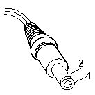
  5. Measure the output voltage at the AC adapter plug.

    DC output plug with pin 1 (centre) and pin 2 (outer sleeve) labelled for measuring the output voltage

    Pin Voltage (Vdc)
    1 +19 to +21
    2 Ground (sleeve)
    • If the voltage is incorrect, but not 0, replace the AC adapter.
    • If the voltage is 0, check the power cord and the power outlet.
    • If the power cord and power outlet are OK, replace the AC adapter.
    • If the voltage is correct, suspect a short circuit or a failure in the computer. Go to Short Circuit Test.

Battery Pack Test #

  1. Remove the battery pack.
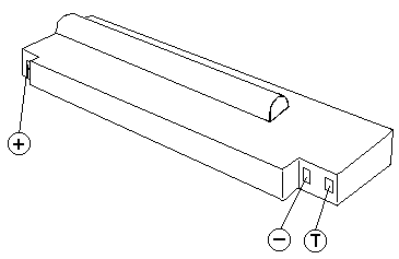
  2. Measure the voltage at the battery contacts as shown below.

    Battery pack with the positive (+), negative (-) and T contacts marked for measuring the voltage

    Contacts Voltage (Vdc)
    + +9.0 to +12.6
    - Ground
  • If the voltage is not correct, charge the battery.
  • If the voltage is not correct after being charged, replace the battery.
  • If the voltage is correct, suspect a short circuit or failure in the computer. Go to the Short Circuit Test.

Use the following procedure to check if the thermal protection has tripped.

  1. Measure the resistance with an ohmmeter between the T and - contacts.
  2. The resistance should not be open (infinity).

    The thermal protection is detected when the temperature exceeds 70°C to 80°C (158°F to 176°F). Wait until the battery temperature becomes normal, then verify the resistance at the battery terminals. If it is open, replace the battery.

Backup Battery Test #

  1. Remove the backup battery.
  2. Measure the voltage on the battery as shown below.

    Coin-cell backup battery whose voltage is measured across its two poles

    Pole Voltage (Vdc)
    + +2.8 to +3.2
    - Ground

If the voltage is not correct, replace the backup battery.

If the voltage is correct, a short circuit or a failure in the system board has occurred. Replace the system board.

Quick Charger Test #

  1. Make sure the AC adapter works correctly by using the AC Adapter Test.
  2. Verify the battery pack is not thermal protected by using the procedure on Battery Pack Test.
  3. Plug the quick charger to the AC adapter. The charger power indicator should turn on.
  4. Install the battery pack, the charging indicator should start blinking.
  5. Within 3.0 hours, the battery pack (not exhausted, standard size) will be fully charged and the charging indicator changes from blinking to constant on.

If the charger does not work as stated above, replace the quick charger.

Car Battery Adapter Test #

  1. Unplug the car adapter from the computer and the cigarette socket.
  2. Measure the cigarette socket voltage. It should be between 9.0 V dc and 18.0 V dc.
  3. Plug the adapter into the car socket. Measure the output voltage of the adapter.

    DC output plug with pin 1 (centre) and pin 2 (outer sleeve) labelled for measuring the output voltage

    Pin Voltage (Vdc)
    1 +19 to +21
    2 Ground (sleeve)
    • If the voltage is incorrect, but not 0, replace the car battery adapter.
    • If the voltage is 0, check that the adapter connector has good contact with cigarette socket. If the connection is good, replace the adapter.
    • If the voltage is correct, and the computer operates with the AC Adapter, replace the car battery adapter.
    • If the voltage is correct, and the computer fails with AC adapter also, perform the AC Adapter Test procedure.

Symptom-to-FRU Index #

Source: Hardware Maintenance Manual Volume 1: Laptop, Notebook, Portable and ThinkPad Computers, p.308

On this page the 710T index is split into Numeric Error Codes, FRU Codes, Beep Symptoms and Miscellaneous Symptoms.

The Symptom-to-FRU Index lists the symptoms and errors and the possible causes. The most likely cause is listed first. Use this index to help you decide which FRUs to have available when servicing a computer.

For errors indicated by the diagnostic tests, see FRU Codes. If the symptom is not listed, go to Undetermined Problems.

In the following error codes, X can be any number.

Note: For IBM devices not supported by ThinkPad 710T diagnostic code, refer to the manual for that device.

Miscellaneous Symptoms #

Source: Hardware Maintenance Manual Volume 1: Laptop, Notebook, Portable and ThinkPad Computers, p.312

Symptom / Error FRU / Action
No beep, Power-on LED not lit, and a blank LCD during POST. (See Power Systems Checkout before replacing any FRUs.)
  1. System Board
  2. DC/DC Card
  3. Power source when failing
No beep, Power-on LED lit, and a blank LCD during POST. (See Power Systems Checkout before replacing any FRUs.)
  1. System Board
  2. Modem Card
No beep during POST but computer runs OK.
  1. System Board (Speaker)
LCD screen unreadable or characters missing pels.
  1. LCD Assembly
  2. System Board
One or more keys do not work.
  1. Keyboard
  2. System Board
Computer does not respond to Pen input.
  1. Pen
  2. LCD Assembly
  3. System Board
LCD backlight not functioning.
  1. Inverter Card
  2. LCD Assembly
  3. Switch and LED Card
  4. System Board
LCD backlight intensity not adjustable.
  1. LCD Assembly
  2. Switch and LED Card
  3. System Board
LCD contrast not adjustable.
  1. LCD Assembly
  2. System Board
  3. Switch and LED Card
System hang or intermittent hang. (See Undetermined Problems before replacing any FRUs.)
  1. Press Reset Button
  2. System Board
  3. Operating System
The computer does not suspend or resume.
  1. System Board
The computer does not power off.
  1. Press Reset Button
  2. System Board
Real-time clock inaccurate.
  1. Backup Battery
  2. System Board
Printer problems. (See Printer Checkout.)
  1. System Board
  2. Parallel Port Device Cable
Serial or parallel port device problems.
  1. Device
  2. Device Cable
  3. System Board
LED incorrectly remains off, but computer runs OK.
  1. Switch and LED Card
  2. System Board
Internal modem card does not communicate with a modem or FAX.
  1. Verify that the setup data defined by the communication software is suitable for the communication.
  2. Modem Card

If the problem remains, see Undetermined Problems.

Undetermined Problems #

Source: Hardware Maintenance Manual Volume 1: Laptop, Notebook, Portable and ThinkPad Computers, p.313

  1. Power-off the computer.
  2. Remove or disconnect one of the following devices:
    • Any external device or cables (including the keyboard)
    • Internal modem card
  3. Power-on computer power and run diagnostic tests.
  4. If the symptom remains, repeat steps 1, 2, and 3 until you find the failing adapter or device.
  5. If all devices are disconnected and the symptom remains, go to Power Systems Checkout. If this does not solve the problem, replace the system board.
  6. If an intermittent problem remains after replacement of the FRUs, consider external electrical noise that can have an effect on the computer. Check that the EMC contacts on the system board are not broken. The contacts are fragile and can be easily damaged.

Numeric Error Codes #

Source: Hardware Maintenance Manual Volume 1: Laptop, Notebook, Portable and ThinkPad Computers, p.308

Symptom / Error FRU / Action
10X
  1. System Board
110 (Check Memory Checkout before changing any device.)
  1. SIMM Card
  2. System Board
111
  1. Option Bus
  2. System Board
161
  1. Refer to Backup Battery Test
  2. System Board
162 (See Checking the Installed Devices List before changing any FRU.)
  1. Check Device Configuration
  2. System Board
  3. Diskette Drive Assembly
  4. Hard Disk Drive Assembly
  5. Diskette Drive Cable
  6. Hard Disk Drive Cable
  7. Modem Card
163
  1. Set Time and Date.
  2. System Board
164 (See Memory Checkout before changing any FRU.)
  1. Check Device Configuration.
  2. SIMM Card
  3. System Board
199
  1. Refer to Checking the Installed Devices List
1XX
  1. System Board
20X
  1. System Board
  2. SIMM Card
21X
  1. SIMM Card
  2. System board
2XX (See Memory Checkout before changing any FRU.)
  1. System Board
  2. SIMM Card
301, 31X
  1. System Board
  2. Keyboard
304, 305
  1. System Board
  2. Mouse
308
  1. System Board
3XX
  1. Keyboard
  2. Mouse
  3. System Board
601, 6XX (Go to the External Diskette Drive Test before changing any FRU.)
  1. System Board
  2. Diskette Drive Assembly
  3. Diskette Drive Cable
602
  1. Diskette Drive Assembly
9XX
  1. System Board
  2. Parallel Device
11XX
  1. System Board
  2. Serial Device
12XX
  1. System Board
  2. Serial Device
  3. Communication Cable
17XX
  1. Disk Drive Assembly
  2. System Board
24XX
  1. System Board
  2. LCD Assembly
5001 – 5016
  1. System Board
  2. LCD Assembly
5017 – 5020
  1. LCD Assembly
  2. System Board
8601, 8603
  1. System Board
  2. Mouse
86XX
  1. Mouse
  2. System Board
101XX
  1. Modem Card
  2. System Board
102XX
  1. LED Card
  2. System Board
  3. Related Devices
I9990305
  1. Operating System
  2. OS device

Beep Symptoms #

Source: Hardware Maintenance Manual Volume 1: Laptop, Notebook, Portable and ThinkPad Computers, p.311

Symptom / Error FRU / Action
Continuous beep.
  1. System Board
One beep and a blank, unreadable, or flashing LCD.
  1. LCD Assembly
  2. System Board
  3. SIMM Card
  4. DC/DC Card
One beep, and the message “Boot source (TPF) cannot be found.”
  1. TPF (in Slot 1)
  2. System Board (TPF Controller)
One beep, and the message “Unable to access boot source.”
  1. TPF (in Slot 1)
  2. System Board (TPF Controller)
One long, two short beeps and a blank or unreadable LCD.
  1. System Board
  2. LCD Assembly
One long beep followed by four short beeps each time you press the power on/off button.
  1. Connect an AC adapter or install a fully charged battery. Computer cannot power-on due to low battery voltage.
One beep every second.
  1. Connect AC adapter or install fully charged battery (allow computer to complete shutdown before changing the battery). Computer is shutting down due to low battery voltage.
Two short beeps.
  1. POST error. See Symptom-to-FRU Index.
Three short beeps.
  1. Move computer to a cooler environment. Battery or computer high temperature threshold has been exceeded.
Four short beeps every five seconds and a blank LCD.
  1. System Board
  2. SIMM Card
  3. Modem Card

FRU Codes #

Source: Hardware Maintenance Manual Volume 1: Laptop, Notebook, Portable and ThinkPad Computers, p.310

If an error is detected by the diagnostic tests, a four-digit FRU code is displayed. The FRU code indicates two suspected FRUs.

Replace the FRU that is indicated by the two leftmost digits, then replace the FRU indicated by the two rightmost digits. No FRU is assigned to code 00. If only one FRU is suspected, the other FRU code is filled with 00.

Use the External Diskette Drive Test to isolate diskette problems to a FRU.

If the problem still remains and the system board has not been replaced, replace the system board.

FRU Code FRU
10 System Board
20 Memory (See Memory Checkout.)
30 Keyboard
31 Numeric Keypad
32 Keyboard, External
33 Mouse
35 Digitizer
36 LCD/Digitizer
40 LCD Assembly
41 External CRT
50 External Diskette Drive
55 Hard Disk Drive
60 System Board
65 IC Card Memory
68 TPF Card
70 System Board, (Printer)
71 System Board, (Printer control)
80 LED Card
82 Switch Card Assembly
85 System Board, (Speaker)
86 DC-DC Card

FRU Removals and Replacements #

Source: Hardware Maintenance Manual Volume 1: Laptop, Notebook, Portable and ThinkPad Computers, p.316

Removals and replacements

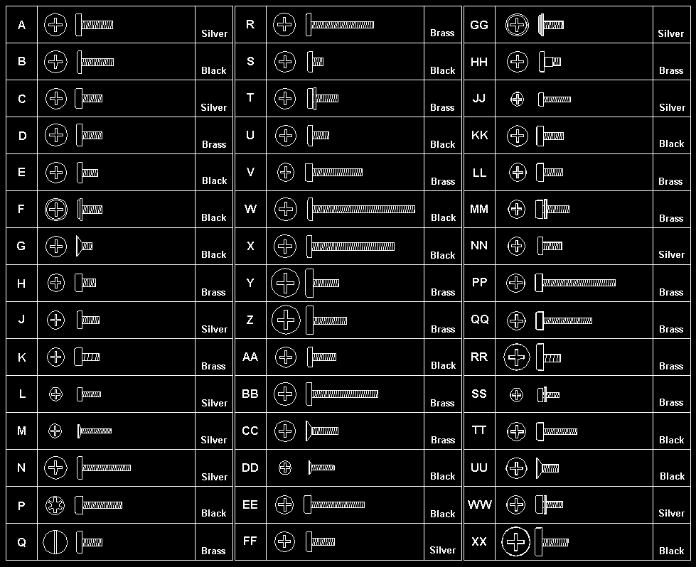
Follow the numerical sequence in the FRU removal sequence list and in the exploded view to remove or disconnect parts in the correct order. The letters in parentheses in the list indicate screw types. See the Screw Size Chart to match the letters to the correct screw type and size before replacing each screw.

Warning Safety Notice 8: Translation

Before removing any FRU, power-off the computer, unplug all power cords from electrical outlets, remove the battery pack, then disconnect any interconnecting cables.

Safety Notice 1: Translation

Before the computer is powered-on after FRU replacement, make sure all screws, springs, or other small parts are in place and are not left loose inside the computer. Verify this by shaking the computer and listening for rattling sounds. Metallic parts or metal flakes can cause electrical shorts.

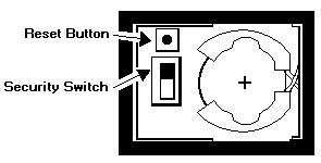
  1. Battery Pack (To replace the backup battery, use a coin to open the backup battery door on the bottom cover. Reset configuration after replacing the backup battery.)
  2. Four Bottom Cover Screws (2-B, 2-W) (At each corner)
  3. Top Cover Assembly
  4. One Bottom Cover Screw (X) (At center)
  5. LCD and Digitizer Cables
  6. LCD Assembly and Shield Cover Assembly
  7. Switch and LED Card
  8. Four Shield Cover Screws (Z) (At corners of shield cover)

    Separate LCD assembly and shield cover (Perform digitizer calibration if the LCD assembly is replaced.)

  9. Standby Battery
  10. System Power Cable
  11. Seven System Board Screws (Y)
  12. System Board (Remove the backup battery, sub battery, DC/DC card and inverter card, and the hard disk drive from the old system board and install them on the new one. Check that the IC card bracket is in place before tightening the board screws. Perform digitizer calibration for the new system board.)
  13. One Screw (Y)
  14. Shield Kit and DC/DC Card
  15. Inverter Card
  16. Four Screws (T) (In system board holding hard disk drive)
  17. Hard Disk Drive

Screw Size Chart #

Use the chart to match the size and shape of the screws in the computer you are servicing.

Screw size chart: drawings of screw types A to XX showing head style, length and colour. Silver: A, C, J, L, M, N, FF, GG, JJ, NN, WW. Black: B, E, F, G, P, S, U, W, X, AA, DD, EE, KK, TT, UU, XX. Brass: D, H, K, Q, R, T, V, Y, Z, BB, CC, HH, LL, MM, PP, QQ, RR, SS. Flat (countersunk) heads: G, M, CC, DD, UU.

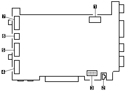
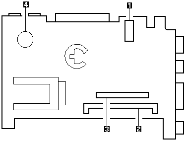
System Board Bottom View (TPF Model) #

Bottom view of the system board (TPF model) with the card connectors and speaker numbered 1 to 4

  1. Inverter Card Connector
  2. SIMM Card Connector
  3. DC/DC Card Connector
  4. Speaker

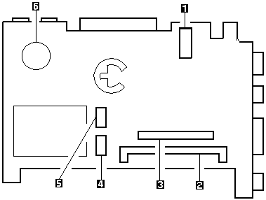
System Board Bottom View (HDD Model) #

Bottom view of the system board (HDD model) with the card connectors, hard disk connectors and speaker numbered 1 to 6

  1. Inverter Card Connector
  2. SIMM Card Connector
  3. DC/DC Card Connector
  4. HDD Connector
  5. HDD Connector
  6. Speaker

Suspend and Resume Modes #

The suspend and resume modes are unique methods to minimize the use of power from the battery. When the computer enters suspend mode, one beep sounds and the Suspend/Resume indicator glows a steady orange. All tasks are stopped and their present states are stored in memory to save power.

When the computer returns to resume mode, the computer restores the same states as when it entered suspend mode. One beep sounds and the indicator glows a steady green when the resume operation is completed.

  • The computer enters suspend mode when:
    • A battery-low condition is detected
    • The Suspend/Resume switch is activated
    • When the computer is not actively used (Auto suspend)
    • The suspend function does not occur when a device is connected to AT Bus, or a modem card is inserted in the IC Card slots.
  • The computer returns to resume mode when the Suspend/Resume switch is switched on. While in the resume state, the indicator blinks.

Parts Listing #

Source: Hardware Maintenance Manual Volume 1: Laptop, Notebook, Portable and ThinkPad Computers, p.322

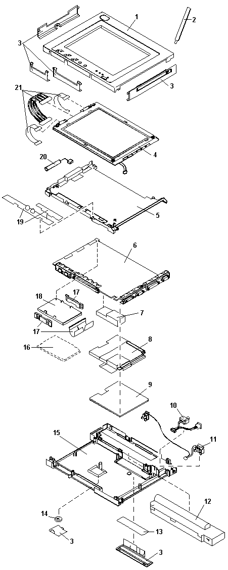
Exploded view of the ThinkPad 710T tablet with its parts numbered 1 to 21

System Unit

IndexPartFRU P/N
1Top Cover Assembly (TPF Model)53G7099
Top Cover (HDD Model)53G7100
2Pen Assembly53G7115
3Cover Group53G7098
4LCD Unit assembly (Includes 3 cables from index 18)48G9685
5Shield Cover53G7101
6System Board (TPF Model)53G6963
System Board (HDD Model)53G6964
7Inverter Card53G7142
8Miscellaneous Kit (See Tools and Miscellaneous)53G6954
9DC/DC Card53G6965
10Switch Cable Assembly53G6966
11Battery Terminal Assembly53G6967
12Battery Pack, Standard Size
U.S., Canada, LA, AG, AP, Spain, and Portugal48G9775
Switzerland48G9776
Norway, Sweden, Finland48G9777
EMEA Others48G9778
Benelux48G9800
Japan53G7143
12Battery Pack, Half Size
U.S., Canada, LA, AG, AP, Spain, and Portugal53G7104
Switzerland53G7105
Norway, Sweden, Finland53G7106
EMEA Others53G7108
Benelux53G7107
Japan53G7110
13SIMM 2MB79F1002
SIMM 4MB79F1003
SIMM 8MB79F1004
14Backup Battery53G7114
15Bottom Cover53G7102
16TPF 5MB, Non pre-loaded48G9899
TPF 10MB, Non pre-loaded48G9900
TPF 15MB, Non pre-loaded49G0000
TPF, Pre-loaded (See the table below.)
17Miscellaneous Kit, Hard Disk Drive48G9780
18Hard Disk Drive, 60MB53G6962
19Switch and LED Card48G9684
20Sub Battery (Except countries below)53G7092
For Switzerland53G7093
For Benelux53G7094
For Japan48G9814
21LCD/ Digitizer Cable48G9686
TPF P/N10MB PenDOS**15MB PenDOS15MB PenPoint**
U.S. English53G715253G715153G7153
U.K. English53G715553G715453G7156
French53G715853G715753G7159
German53G716153G716053G7162
Italian53G716453G716353G7165
Spanish53G716753G716653G7168
Japanese53G717053G716953G7171

** PenPoint is a trademark of the GO Corporation.

** PenDOS is a trademark of the Communications Intelligence Corporation.

External FRUs

PartFRU P/N
External Diskette Drive (without cable)48G9896
External Diskette Drive Cable48G9897
Quick Charger48G9820
Car Adapter
U.S./Canada/LA/Japan07G1190
EMEA35G3304
AC Adapter07G1246
AP/EMEA07G1851
Japan (2-Pin)07G1248

Tools and Miscellaneous

No special tools are needed to service the computer.

The following lists the miscellaneous parts kits. (Numbers in parentheses show quantity)

PartFRU P/N
Screw kit53G7113
LCD screw (10)
System board and DC/DC screw (10)
Bottom cover screw long (10)
Bottom cover screw short (10)
Bus connector stud (10)
Connector stud screw (10)
Keyboard, Mouse screw (10)
FDD screw (10)
HDD bracket screw (10)
System board bracket screw (10)
Knob Sheet53G7103
Knob sheet assembly (1) (Screen control button top)
Label Group53G6952
Serial No. label, blank (1)
Artwork blank (1)
Information label, H (1)
Information label, H for Japan (1)
Information label, T (1)
Information label, T for Japan (1)
Battery CSU label (1)
Bracket Kit53G6953
I/O bracket assembly (1)
AT BUS,KBD/mouse bracket (1)
IC card bracket (1)
HDD bracket (1)
Miscellaneous Kit53G6954
Battery knob (1)
Screw cap (1)
Front foot (1)
Rear foot (1)
DC/DC shield (1)
Tri-Connector Wrap Plug72X8546
PC Test Card35G4703
Audio Wrap Cable66G5180
Screwdriver Kit95F3598

Power Cords

Warning: Use only the power cord certified for your country.

IndexCountryFRU P/N
1Colombia, U.S., Venezuela13F9959
Japan, 2-pin6454377
Japan, 3-pin65F0031
2Hong Kong, Singapore, U.K.14F0033
3France, Germany, Spain13F9979
4Italy14F0069
5Australia, New Zealand13F9940
6Denmark13F9997
7Israel14F0087
8Bangladesh, Pakistan, Sri Lanka, South Africa14F0015
9Switzerland14F0051
10Thailand1838574

Safety Notice 8 #

Warning Safety Notice 8

Before removing any FRU, power-off the computer, unplug all power cords from electrical outlets, remove the battery pack, then disconnect any interconnecting cables.

Avant de retirer une unité remplaçable en clientèle, mettez le système hors tension, débranchez tous les cordons d'alimentation des socles de prise de courant, retirez la batterie et déconnectez tous les cordons d'interface.

Die Stromzufuhr muß abgeschaltet, alle Stromkabel aus der Steckdose gezogen, der Akku entfernt und alle Verbindungskabel abgenommen sein, bevor eine FRU entfernt wird.

Prima di rimuovere qualsiasi FRU, spegnere il sistema, scollegare dalle prese elettriche tutti i cavi di alimentazione, rimuovere la batteria e poi scollegare i cavi di interconnessione.

Antes de quitar una FRU, apague el sistema, desenchufe todos los cables de las tomas de corriente eléctrica, quite la batería y, a continuación, desconecte cualquier cable de conexión entre dispositivos.

Safety Notice 1 #

Warning Safety Notice 1

Before the computer is powered-on after FRU replacement, make sure all screws, springs, or other small parts are in place and are not left loose inside the computer. Verify this by shaking the computer and listening for rattling sounds. Metallic parts or metal flakes can cause electrical shorts.

Avant de remettre l'ordinateur sous tension après remplacement d'une unité en clientèle, vérifiez que tous les ressorts, vis et autres pièces sont bien en place et bien fixées. Pour ce faire, secouez l'unité et assurez-vous qu'aucun bruit suspect ne se produit. Des pièces métalliques ou des copeaux de métal pourraient causer un court-circuit.

Bevor nach einem FRU-Austausch der Computer wieder angeschlossen wird, muß sichergestellt werden, daß keine Schrauben, Federn oder andere Kleinteile fehlen oder im Gehäuse vergessen wurden. Der Computer muß geschüttelt und auf Klappergeräusche geprüft werden. Metallteile oder -splitter können Kurzschlüsse erzeugen.

Prima di accendere l'elaboratore dopo che é stata effettuata la sostituzione di una FRU, accertarsi che tutte le viti, le molle e tutte le altri parti di piccole dimensioni siano nella corretta posizione e non siano sparse all'interno dell'elaboratore. Verificare ciò scuotendo l'elaboratore e prestando attenzione ad eventuali rumori, eventuali parti o pezzetti metallici possono provocare cortocircuiti pericolosi.

Antes de encender el sistema despues de sustituir una FRU, compruebe que todos los tornillos, muelles y demás piezas pequeñas se encuentran en su sitio y no se encuentran sueltas dentro del sistema. Compruébelo agitando el sistema y escuchando los posibles ruidos que provocarían. Las piezas metálicas pueden causar cortocircuitos eléctricos.