ThinkPad Laptops

ThinkPad 500

Machine Type 2603 · 1993 · 33 sections

IBM's 1993 monochrome subnotebook, pairing a 50 MHz 486SLC2 with a 64-shade grey-scale screen and an 85MB or 170MB hard disk in a case of under four pounds. There is no internal diskette drive: an external drive and cable came with it.

This transcribed historical service reference may contain incomplete captures. The linked original manuals remain authoritative.

Service Reference

Product Overview #

Compiled from a hardware survey and IBM's product records. A dash means no source records the value.

ThinkPad 500 specifications
Specification ThinkPad 500
Released June 1993
Processor IBM 486SLC2, 50 MHz (soldered QFP package)
Chipset Western Digital WD7855LV
Bus AT bus
Memory Standard 4 MB; maximum 12 MB; IC DRAM card, 1 slot
Storage 2.5" IDE: 85 or 170 MB; drive adapter required
Display 7.4" passive matrix greyscale (64 shades), 640 × 480
Graphics Western Digital WD90C26, 512 KB video memory
Audio PC speaker
Main battery
  • Sealed lead-acid (standard)
  • NiMH (optional, later standard)
CMOS battery Soldered lithium coin cell
Power connector
  • Barrel jack (16.3 V, 1.84 A, centre negative)
  • IBM 59G7988 AC adapter
Media drives None; external floppy drive supported
PC Card slots
  • 1 × PCMCIA (Type II)
  • Intel SE82365SL controller
Networking None
Ports
  • Parallel
  • VGA out (needs a dongle)
  • External floppy/serial port
BIOS Phoenix BIOS
Pointing device TrackPoint II

Status Indicators #

Source: Hardware Maintenance Manual Volume 1: Laptop, Notebook, Portable and ThinkPad Computers, p.252

IBM's table pairs a symbol for each indicator with its meaning. The symbols are drawn on PDF page 252 of the Hardware Maintenance Manual, Volume 1; in the manual's order, the indicators show:

  • Battery almost discharged
  • Battery is charging (this indicator is on whenever the AC adapter is connected to the computer)
  • Computer is powered-on
  • Computer is in suspend mode
  • Hard disk drive is active
  • Diskette drive is active
  • Keyboard is in Num Lock mode
  • Keyboard is in Caps Lock mode
  • Keyboard is in Scroll Lock mode

General Checkout #

Source: Hardware Maintenance Manual Volume 1: Laptop, Notebook, Portable and ThinkPad Computers, p.244

Start here. The procedures on this page are transcribed from the ThinkPad 500 (2603) chapter of IBM's Hardware Maintenance Manual, Volume 1 (PDF pages 243–268), with the common device checkouts from the same volume.

Important

An external diskette drive must be attached to the computer to run the diagnostics program from a diskette. If an external diskette drive is not attached to the computer, do the following.

  1. Run the POST (Power-On Self Test).
  2. If you receive an error, go to Symptom-to-FRU Index.
  3. If you suspect an undetermined problem, go to Undetermined Problems.
  1. Power-off the computer and all external devices.
  2. Check all cables and power cords for correct connection.
  3. Insert the Advanced Diagnostics diskette into the diskette drive.
  4. Power-on all external devices.
  5. Power-on the computer and check for one short beep at the end of POST with a clear and readable diagnostics menu displayed. If you did not get the correct responses, go to Symptom-to-FRU Index.
  6. Run the advanced diagnostics tests. For information on how to disable the password, see Power-On Password.
  7. Find your symptom below, then go to the appropriate page. Otherwise, see Symptom-to-FRU Index, then go to Undetermined Problems.
Symptom Go to ...
Error Code or Message Symptom-to-FRU Index
Configuration Problem Checking the Installed Devices List
Power Problem Power Systems Checkout
Memory Problem Memory Checkout
TrackPoint II Problem TrackPoint II Checkout

Note: For information about how to run diagnostics, error messages, passwords, and various other tests and service checks, go to Related Service Procedures.

Memory Checkout #

Source: Hardware Maintenance Manual Volume 1: Laptop, Notebook, Portable and ThinkPad Computers, p.245

001
  • Power-off (O) the computer and wait 10 seconds.
  • Reseat the memory module.
  • Insert the Advanced Diagnostics diskette into the diskette drive.
  • Power-on (|) the computer.
  • Make a note of any error code you receive.

DID YOU RECEIVE A 20X XXXXXXXX XXXXXXXX OR 02XX POST ERROR OR FAILURE SYMPTOM?

Yes — go to Step 003. No — go to Step 002.

002

Go to Step 006.

003

IS A MEMORY MODULE INSTALLED?

Yes — go to Step 005. No — go to Step 004.

004

Replace the system board. Press Fn and F1 to set the time and date to remove the 16X errors.

005

Replace the memory module kit.

If the error remains, replace the system board. Press Fn and F1 to set the time and date and remove the 16X errors.

006

(From step 002)

  • If you need to bypass an error, press Esc or F1.
  • If you cannot continue, you might have a keyboard problem; go to Symptom-to-FRU Index.

DID THE ADVANCED DIAGNOSTICS MENU APPEAR?

Yes — go to Step 008. No — go to Step 007.

007

You may have a diskette drive problem; go to Symptom-to-FRU Index.

008
  • Press 0 (SYSTEM CHECKOUT), then press Enter.
  • Follow the screen instructions.

Note: Ignore a 199 error.

  • Press 0 (RUN TESTS ONE TIME), then press Enter.
  • Press 2 (MEMORY), then press Enter.

DID YOU RECEIVE A 2XX ERROR OR FAILURE SYMPTOM?

Yes — go to Step 010. No — go to Step 009.

009

Go to Step 011.

010

Go to Step 003.

011

(From step 009)

DID THE SYSTEM CHECKOUT MENU APPEAR AT THE END OF TEST?

Yes — go to Step 013. No — go to Step 012.

012

You may have a power source problem; go to Power Systems Checkout.

013

The Advanced Diagnostics tests finished without detecting a failure. If you suspect an intermittent problem, start an error log. If you need instructions, go to Error Log.

Checking the Installed Devices List #

Source: Hardware Maintenance Manual Volume 1: Laptop, Notebook, Portable and ThinkPad Computers, p.253

If an adapter or device is missing from the Installed Devices list and you are able to add it to the list, do so and continue with the diagnostic tests.

If an adapter or device is missing from the installed devices list and you cannot add it to the list, you might have one of the following conditions:

  • The diagnostic code for the missing device is not on your Advanced Diagnostics diskette.
  • The missing device is a 5.25-Inch External Diskette Drive Adapter, or another unrecognizable adapter.
  • The missing device is defective.
  • The bus adapter is defective.
  • The adapter or device is not an IBM product.

If the number of drives installed in the computer differs from the number shown in the installed devices list, an error can occur during the diagnostic tests. Restart the computer and correct the drive information in the Set Configuration menu before running the diagnostic tests.

TrackPoint II Checkout #

Source: Hardware Maintenance Manual Volume 1: Laptop, Notebook, Portable and ThinkPad Computers, p.482

  • If the TrackPoint II does not work, check the configuration. If the configuration of the TrackPoint II is set to Disabled or Off, change it to Enable or On.

    If the problem remains, continue.

    Note: TrackPoint II automatically compensates to adjust the pointer sensor. This causes the pointer to move slightly on the screen and then stop. Pointer movement might occur when a slight, steady pressure is applied to the TrackPoint II pointer when the computer is powered-on or running, or when exceeded temperature range requires re-adjustment.

  • If the cursor floats or moves erratically, power-off and disconnect the mouse. Power-on the computer. If the problem goes away, replace the mouse. If the problem remains, replace the keyboard.
  • For click button or pointing stick problems:

    1. Go to the Easy-Setup screen.
    2. Select an item with the pointing stick.
    3. Press either left or right click button.
    4. Verify that both buttons work correctly.

    If the pointing stick or the click button does not work, do the following.

    1. Reseat the keyboard cables.
    2. Replace the keyboard.
    3. Replace the interposer card (355x, 360x, 750x, 755x).
    4. Replace keyboard control card (720).
    5. Replace the system board.

External Keyboard / Auxiliary Input Device Checkout #

Source: Hardware Maintenance Manual Volume 1: Laptop, Notebook, Portable and ThinkPad Computers, p.477

The following auxiliary input devices may be available for IBM ThinkPad models.

  • Numeric keypad
  • Mouse (PS/2 compatible)
  • External keyboard (with Keyboard/Miniature Mouse cable)
  • If you suspect a problem with any of the auxiliary input devices (listed above), replace the device. If the problem is not corrected, replace the following FRUs one at a time to correct the problem.

    • Keyboard control card
    • System board
  • If the computer receives an incorrect keyboard response, remove other external devices, check the keyboard connections, and recheck the keyboard responses. If the problem remains, replace the following FRUs one at a time to correct the problem.

    • Keyboard
    • Keyboard control card
    • System board
  • If a 00030100 error message appears, power-off the computer and the external devices. Then power-on the computer before you power-on the external devices.

Printer Checkout #

Source: Hardware Maintenance Manual Volume 1: Laptop, Notebook, Portable and ThinkPad Computers, p.480

  1. Make sure the printer is correctly connected and is powered-on.
  2. Run the printer self-test.

If the printer self-test does not run correctly, the problem is in the printer. Refer to the printer service manual.

If the printer self-test runs correctly, do the following.

  1. Verify the port settings in configuration.
  2. Install a wrap plug on the port (indicated in configuration) and run the advanced diagnostic tests.
  3. If the advanced diagnostic tests (with the wrap plug installed) do not detect a failure, replace the printer cable. If the problem is not corrected, replace the system board.

Fax/Modem Checkout #

Source: Hardware Maintenance Manual Volume 1: Laptop, Notebook, Portable and ThinkPad Computers, p.478

001
  • Power-off the computer.
  • Ensure that the modem is installed correctly.
  • If the modem never worked in customer mode, ensure that all drivers are loaded correctly onto the computer.
  • Ensure that the communication program is supported on the computer.
  • Ensure that the public switch telephone network (PSTN) cable and the data access arrangement (DAA) cable, if installed, are connected correctly.

If you need to correct one of the above conditions, do so now; then continue.

Note: PCMCIA cards can be inserted and removed while the system is powered on.

  • Power-on the system.
  • Insert the IBM Data/FAX Modem diskette into the default diskette drive.
  • If you are servicing a High Speed Internal Data/Fax Modem (Models FC3632 and FC3650), at the DOS prompt (for example, A:\), type IBMDIAG; then press Enter.
  • If you are servicing a PCMCIA Data/FAX Modem (Models FC3634 and FC3635), at the DOS prompt (for example, A:\), type ESTDIAG; then press Enter.
  • Follow the instructions on the screen. (If you need help, press F1.)

DID THE DIAGNOSTIC TESTS DETECT AN ERROR?

Yes — go to Step 003. No — go to Step 002.

002

The diagnostic tests have completed successfully. If you suspect a problem, go to Step 004.

003

Go to the Symptom-to-FRU Index for the computer you are servicing.

004
  • Check the PSTN cable and the DAA cable, if installed, for continuity.

IS THE CABLE(S) GOOD?

Yes — go to Step 006. No — go to Step 005.

005

Replace the defective cable(s).

006
  • Have the customer transmit a call.

WAS THE CALL TRANSMITTED SUCCESSFULLY?

Yes — go to Step 008. No — go to Step 007.

007

Go to Step 011.

008
  • Have the customer receive an incoming call on the modem.

WAS THE INCOMING CALL RECEIVED?

Yes — go to Step 010. No — go to Step 009.

009

Go to Step 014.

010

The diagnostic tests have completed successfully. If you still suspect a problem that is not software related, replace the External DAA; then replace the modem.

011
  • Have the customer transmit a call at a lower speed.

WAS THE CALL TRANSMITTED SUCCESSFULLY?

Yes — go to Step 013. No — go to Step 012.

012

If installed, replace the external DAA. If you do not have an external DAA installed, or replacing the external DAA does not correct the problem, replace the modem.

013

Have the telephone line checked.

014
  • Have the customer receive an incoming call on the modem at a lower speed.

WAS THE INCOMING CALL RECEIVED?

Yes — go to Step 016. No — go to Step 015.

015

If installed, replace the external DAA. If you do not have an external DAA installed, or replacing the external DAA does not correct the problem, replace the modem.

016

Have the telephone line checked.

Power Systems Checkout #

Source: Hardware Maintenance Manual Volume 1: Laptop, Notebook, Portable and ThinkPad Computers, p.247

To check the system power, do the following.

  1. Power-off the computer.
  2. Remove the battery from the computer.
  3. Check the battery voltage. The voltage should be 10.8 V dc.

    If the voltages are not correct, try recharging the battery pack.

    If the voltages are correct, continue with the next step to test the AC adapter voltage.

  4. Unplug the AC adapter from the computer.
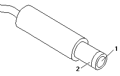
  5. Measure the voltage at the points shown.

    Plug of the AC adapter cable with measuring points 1 and 2 labelled

    V dc + Lead − Lead
    +16.3 2 1

    If the voltage is not correct, replace the AC adapter.

    If the voltage is correct, go to Undetermined Problems.

Power Management Features #

Source: Hardware Maintenance Manual Volume 1: Laptop, Notebook, Portable and ThinkPad Computers, p.248

Press Func+F3 to select Power Management setup (any time after the computer is powered-on).

Important

Before using the power saving features, be sure to read and observe the following precautions:

  • If you enter Suspend or Hibernate mode with a diskette inserted in the diskette drive, the same diskette must be installed in the drive before attempting to resume normal operation.
  • If you enter Suspend or Hibernate mode with a PCMCIA card inserted in the PCMCIA slot, the same PCMCIA card must be installed in the slot before attempting to resume normal operation.

    Hibernate mode does not save/restore the status of PCMCIA cards. When you resume normal operation from Hibernate mode, the PCMCIA card is no longer configured and will not be recognized by the computer.

  • If the computer is connected to a Local Area Network (LAN) that periodically polls for station activity, the LAN-connection may be terminated while the computer is in Suspend or Hibernate mode. Any further attempt to access the network results in a brief delay and the computer appears to hang (up to 1 minute, depending on the network). After the delay, an error is displayed. Follow the instructions on the screen to restore normal operation.
  • Any software program that was running over the LAN is not re-entered when you resume normal operation from Hibernate or Suspend modes.

Power-On Self Test (POST) #

Source: Hardware Maintenance Manual Volume 1: Laptop, Notebook, Portable and ThinkPad Computers, p.253

Each time you power-on the computer, the POST is initiated. The POST takes up to 15 seconds to complete, depending on the options installed.

The POST checks the following: system board, memory, display, keyboard, diskette drive, hard disk drive, parallel port, and serial port.

To start the POST, power-on the computer.

  1. You will hear one short beep when the POST successfully ends.

    If the POST cannot be completed successfully, an error message appears on the display accompanied by the Configuration Utility box requesting the user to press the Esc or Enter key. If the Esc key is pressed, the computer bypasses the error and attempts to complete the POST. If the Enter key is pressed, the Configuration Utility is shown. The user can then try to correct the error. If a critical error is encountered, the POST is halted.

  2. The computer attempts to load the operating system as customized.

Loading the Diagnostics Diskette #

Source: Hardware Maintenance Manual Volume 1: Laptop, Notebook, Portable and ThinkPad Computers, p.254

To load the diagnostics diskette, insert the Advanced Diagnostics diskette into the diskette drive and power-on the computer.

Accessing the Diagnostic Tests

To access diagnostic tests from the SELECT AN OPTION Menu, do the following.

  1. Select 0 (SYSTEM CHECKOUT), then press Enter.
  2. At the Installed Devices menu, press (Y), then press Enter.
  3. The SYSTEM CHECKOUT menu is then displayed.
  4. Select 0 or 1 from the SYSTEM CHECKOUT menu.
  5. Select the device to be tested.

Formatting the Hard Disk Drive #

Source: Hardware Maintenance Manual Volume 1: Laptop, Notebook, Portable and ThinkPad Computers, p.254

Hard disk drives normally contain tracks in excess of their stated capacity to allow for defective tracks. The user is notified by a diagnostic message when the defect limit has been reached and service is recommended.

The Advanced Diagnostics Format program is different from the operating system format program. Before the customer can transfer information from the backup diskettes to the hard disk drive, the hard disk drive must be formatted using the operating system format program. Have the customer refer to the operating system manual for a description of the hard disk preparation commands.

Warning: All data on the selected hard disk drive will be destroyed during a format operation or surface analysis.

After formatting the hard disk drive, copy the System files from the Diagnostics diskette to the hard disk drive.

Restoring the TP500 Subdirectory

The TP500 subdirectory on the Diagnostics diskette and hard disk drive contains the following:

  • Installation utilities
  • Introductory program
  • Other utilities
  • OS/2 PCMCIA drivers

If the hard disk drive is reformatted or the files in the TP500 subdirectory on the hard disk drive are corrupted, copy the TP500 subdirectory on the Diagnostics diskette to the hard disk drive. To create a TP500 subdirectory on the hard disk drive and copy the files, do the following:

Important

The following is required to complete this procedure:

  • DOS or OS/2 must be installed on the hard disk drive.
  • An external diskette drive must be attached to the computer.
  1. Power-on the computer.
  2. At the DOS prompt, type md c:\TP500 then press Enter. A TP500 subdirectory is created on the hard disk drive.
  3. Insert the Diagnostics diskette into the diskette drive.
  4. Type copy a:\TP500\*.* c:\TP500\*.* then press Enter. The files are copied from the TP500 subdirectory on the Diagnostics diskette to the TP500 subdirectory on the C drive.

External Display Self-Test #

Source: Hardware Maintenance Manual Volume 1: Laptop, Notebook, Portable and ThinkPad Computers, p.476

If the display problem occurs only when using an external display, use the following instructions to correct the problem.

Note: Before you replace a display, check the following list to see if it is connected correctly.

  • 8506 and 8508 displays must be connected to an Image Adapter/A or an Image-I Adapter/A.
  • 63XX and 85XX systems support either 63XX or 85XX displays.
  • 85XX systems with an XGA-2 adapter support 95XX displays.
  • 95XX systems support either 63XX, 85XX, or 95XX displays.
  • ThinkPad models support either 85XX or 95XX displays.

If the screen is rolling, replace the display assembly. If that does not correct the problem, replace FRUs in the following order until the problem goes away:

  1. Video card
  2. Display adapter (any type)
  3. System board
  4. Bus adapter (if used)

If the screen is not rolling, run the display self-test as follows:

  1. Power-off the computer and display.
  2. Disconnect the display signal cable.
  3. Power-on the display.
  4. Set the contrast to its maximum position.
  5. Set the brightness control to the center detent position.

Check for the following conditions:

  • You should be able to vary the screen intensity by adjusting the contrast and brightness controls.
  • The screen should be white or light gray, with a black margin (test margin) on the screen.

    Note: The location of the test margin varies with the type of display. The test margin might be on the top, bottom, or one or both sides.

If you do not see a test margin on the screen, replace the display. If there is a test margin on the screen, replace the system board.

Note: On ThinkPad Models 700, 700C, 720C, 720C, do the following:

  1. Video card
  2. System board

Symptom-to-FRU Index #

Source: Hardware Maintenance Manual Volume 1: Laptop, Notebook, Portable and ThinkPad Computers, p.249

On this page IBM's index continues in separate sections: Numeric Error Codes, Beep Symptoms, Miscellaneous Symptoms and Undetermined Problems.

The Symptom-to-FRU Index lists symptoms, errors, and the possible causes. The most likely cause is listed first. Use this index to help you decide which FRUs to have available when servicing the computer.

In the following error codes, X can be any number.

Note: For IBM devices not supported by the ThinkPad diagnostic code, refer to the manual for that device.

Miscellaneous Symptoms #

Source: Hardware Maintenance Manual Volume 1: Laptop, Notebook, Portable and ThinkPad Computers, p.250

Symptom/Error FRU/Action
Blank screen
  1. Battery
  2. AC Adapter
  3. Memory Option
  4. System Board
Display problems
  1. External Display, if installed
  2. External Display Power Cord
  3. LCD Assembly
LCD contrast not adjustable
  1. LCD Assembly
  2. System Board
Keyboard problems
  1. Reseat cables
  2. Keyboard
  3. System Board
Mouse problems
  1. Reseat cable
  2. Mouse
  3. System Board
Diagnostic tests hang
  1. Battery
  2. AC Adapter
  3. Memory Option
  4. System Board
Blinking cursor only
  1. Diskette Drive
  2. System Board
No beep or continuous beeps. (See Power Systems Checkout before replacing any FRUs.)
  1. System Board
  2. Memory Option
Diskette drive bypassed
  1. Reseat DASD/Serial Cable
  2. Diskette Drive
Can't read diskette
  1. Diskette Drive
Hard disk problem
  1. Hard Disk
Printer problem
  1. Check Configuration
  2. Parallel Port
  3. System Board
Communication or plotter problem
  1. Check Configuration
  2. Serial Port
  3. PCMCIA Device
  4. System Board

Undetermined Problems #

Source: Hardware Maintenance Manual Volume 1: Laptop, Notebook, Portable and ThinkPad Computers, p.251

If you have not already done so, go to Power Systems Checkout and check the AC adapter and battery voltages.

If the AC adapter and battery voltages are correct and the problem remains, do the following.

  1. Power-off the computer.
  2. Remove or disconnect one of the following devices:
    • Any external devices or cables
    • Any PCMCIA device
  3. Power-on the computer.
  4. If the symptom remains, repeat steps 1, 2, and 3 until you find the failing adapter or device.
  5. If this does not solve the problem, replace the system board.

Error Log #

Source: Hardware Maintenance Manual Volume 1: Laptop, Notebook, Portable and ThinkPad Computers, p.255

Use the following steps to create an error log, run the diagnostic tests, and automatically record any error messages in an error log. This procedure is normally used to diagnose an intermittent problem.

Note: The errors must be logged to a diskette drive or to a printer. If recording errors on a diskette, use a copy of the Advanced Diagnostics diskette that is not write-protected. Do not run any diskette tests when logging to a diskette drive. Do not run a parallel port test when logging to a printer.

Creating the Error Log

  1. Insert the Advanced Diagnostics diskette into the diskette drive.
  2. Press 0 (SYSTEM CHECKOUT), then Enter.
  3. Depending on the options installed in the computer, questions about attached devices may appear on the display. Answer as required; then press Enter.
  4. Press Y or N (IS THE LIST CORRECT (Y/N)?), then Enter.
  5. Press 2 (LOG UTILITIES), then Enter.
  6. Press 0 (START ERROR LOG), then Enter.
  7. Press 0 or 1 (LOG TO DISKETTE, OR PRINTER (0/1)?), then Enter.
  8. If you are logging to diskette, press A (ENTER THE DRIVE ID FOR ERROR LOG?), then Enter.
  9. Press 9 (END LOG UTILITIES), then Enter.

Starting the Test

  1. Press 1 (RUN TESTS MULTIPLE TIMES), then Enter.
  2. Select the device you suspect has a failure, then press Enter.
  3. Select the number of times the test is to be run; then press Enter.
  4. Press N (WAIT EACH TIME AN ERROR OCCURS (Y/N)?), then Enter.
  5. Follow any instructions on the display and select all available tests.

    Note: Do not press any keys during the keyboard test.

  6. To end (RUN TEST CONTINUOUSLY), press and hold the Ctrl key; then press the Pause key. The computer will complete testing and return to the Installed Devices menu.

Display the Error Log

  1. Depending on the options installed in the computer, questions about attached devices will appear on the display. Answer as required; then press Enter.
  2. Press Y or N (IS THE LIST CORRECT (Y/N)?), then Enter.
  3. Press 2 (LOG UTILITIES), then Enter.
  4. Press 2 (DISPLAY LOG), then Enter.
  5. Press A (ENTER THE DRIVE ID FOR ERROR LOG?), then Enter.
  6. If no errors occurred, the Log Utilities menu appears. If errors are displayed, go to Symptom-to-FRU Index.

Numeric Error Codes #

Source: Hardware Maintenance Manual Volume 1: Laptop, Notebook, Portable and ThinkPad Computers, p.249

Symptom/Error FRU/Action
02X, 101, 107
  1. Battery
  2. AC Adapter
  3. Memory Option
  4. System Board
102, 103, 104, 106, 108, 109, 190 (Press Func and F1 to set the time and date and remove any 16X errors.)
  1. System Board
111
  1. Memory Option
161, 163
  1. Set Configuration
  2. Battery
  3. System Board
162
  1. Any Device (Check the installed devices list for a missing device.)
  2. System Board
1XX (not listed above)
  1. System Board
2XX
  1. Memory Option
3XX
  1. Keyboard
  2. System Board
6XX
  1. Diskette Drive
  2. System Board
9XX, 10XX
  1. Any External Parallel Device
  2. System Board
11XX, 12XX
  1. Any External Serial Device
  2. PCMCIA Device
  3. System Board
17XX
  1. Hard Disk
  2. System Board
24XX
  1. Display
  2. System Board
86XX
  1. Keyboard
  2. System Board

Beep Symptoms #

Source: Hardware Maintenance Manual Volume 1: Laptop, Notebook, Portable and ThinkPad Computers, p.250

Symptom/Error FRU/Action
One long and one short beep
  1. Memory Option
Two long beeps, 3 short beeps, and a blank screen
  1. External Display, if installed
  2. External Display Power Cord
  3. LCD Assembly
  4. System Board
Multiple short beeps
  1. Keyboard (stuck key)
One short beep with a display problem. (For external displays, see External Display Self-Test before replacing FRUs.)
  1. External Display
  2. Display Power Cord
  3. LCD Assembly
One long and multiple short beeps
  1. External Display, if installed
  2. External Display Power Cord
  3. LCD Assembly

FRU Removals and Replacements #

Source: Hardware Maintenance Manual Volume 1: Laptop, Notebook, Portable and ThinkPad Computers, p.260

The exploded view that this sequence follows is not reproduced on this page; it is on PDF page 262 of the Hardware Maintenance Manual, Volume 1.

Removals and replacements

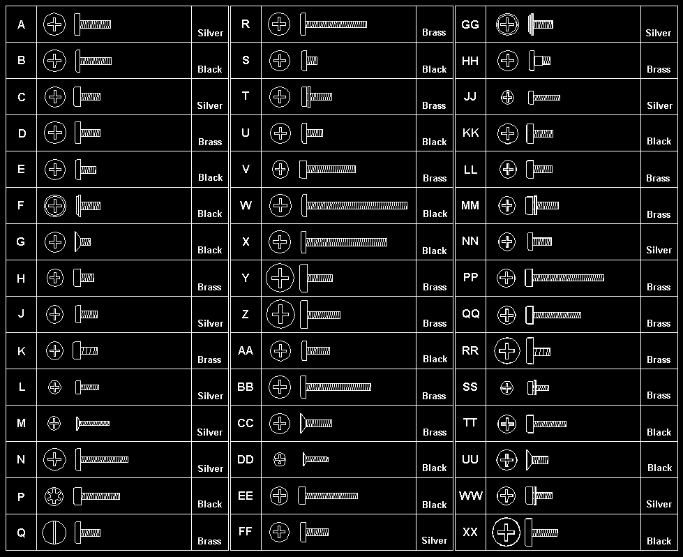
Follow the numerical sequence in the FRU removal sequence list and the exploded view to remove or disconnect parts in the correct order. The letters in parentheses in the list indicate screw types. See the Screw Size Chart to match the letters to the correct screw type and size before replacing each screw.

Warning Safety Notice 8: Translation

Before removing any FRU, power-off the computer, unplug all power cords from electrical outlets, remove the battery pack, then disconnect any interconnecting cables.

Safety Notice 1: Translation

Before the computer is powered-on after FRU replacement, make sure all screws, springs, or other small parts are in place and are not left loose inside the computer. Verify this by shaking the computer and listening for rattling sounds. Metallic parts or metal flakes can cause electrical shorts.

Note: Be sure the LED cable is not in the battery compartment of over the keyboard supports.

  1. Battery Pack
  2. Lift Keyboard (Pry up front of keyboard with a small plastic screwdriver.)
  3. Three Ribbon Cables

    Remove Keyboard

    Remove Hard Disk Drive Ribbon Cable (Use caution; the cable pins can scratch the LCD.)

  4. Fourteen Bottom Cover Screws (6-G, 2-DD, 6-EE)

    • (2-G screws near mouse buttons)
    • (1-D screw in center)
    • (1-D screw near power button icon)
    • (6-EE screws around bottom cover perimeter)
  5. Bottom Cover
  6. Ribbon Cable

    (Open the IC DRAM cover on the bottom. From the bottom, keep pressure on the system board while removing the cable.)

    (If replacing the hard disk drive or bottom cover, remove the 4-G screws near FCC notice. Caution; copper flakes easily from the screws.)

  7. Hard Disk Drive
  8. Mouse Button Cable (Pull connector, not the cable.)
  9. Three Cables
  10. System Board (Note plastic screw inserts location.)
  11. Two Threaded Spacers (In power card)
  12. Power Card (Note washer placement.)

Locations #

The drawings these numbers refer to are not reproduced on this page; they are on PDF pages 263–264 of the Hardware Maintenance Manual, Volume 1.

Front View

  1. Top Cover Release Latches
  2. Contrast Control Buttons
  3. Brightness Control Buttons
  4. On/Off Button
  5. PCMCIA Eject Button
  6. PCMCIA Slot
  7. Pointing Stick
  8. Right Button (pointing stick)
  9. Memory Card Access Panel
  10. Left Button (pointing stick)
  11. Battery
  12. Status Indicator LEDs

System Board

  1. Pointing Device Connector
  2. Hard Disk Drive Connector
  3. Keyboard Connector
  4. Sense Connector
  5. Wobble Connector
  6. LED Connector
  7. Power Card Connector
  8. LCD Data Connector
  9. Parallel Port Connector
  10. PCMCIA Connector
  11. IC DRAM Card Socket
  12. External Display Connector
  13. LCD Power Connector
  14. Diskette Drive/Serial Port Connector

Utilities #

The system is configured with several utility programs. These programs provide added function that enhance the usability of the system. It is recommended that you backup these programs to prevent loss of data. Use the INTRO program shipped with the computer to backup the utilities. The utility programs are:

SIMUL

Allows you to enable/disable simultaneous display on both the LCD and external monitor.

Note: The computer will not enter Suspend/Resume while in the Simultaneous mode. You must exit Simultaneous mode before Suspend/Resume is allowed. Also, the Func + F7 function is not recognized until you exit the Simultaneous mode.

EPP2
Provides Enhanced Parallel Port Utility. This utility needs to be added to the AUTOEXEC.BAT and CONFIG.SYS if the option attached to the parallel port supports the enhanced parallel port mode.
PHDISK

Prepares the hard disk drive for the hibernation feature, including formatting and the marking of defective areas. A partition is reserved on the hard disk drive to save data before the computer enters Hibernation mode.

Warning: Running this utility causes loss of data on the hard disk drive. It is important that the customer backup all data prior to using this utility.

Important

Run the PHDISK utility if you change the operating environment, reformat the hard disk drive, or add additional memory.

PCMCIA Drivers
IBM22SS01.SYS and PCMCIA.SYS provides the ability to use PCMCIA cards in an OS/2 environment.

Parts Listing #

Source: Hardware Maintenance Manual Volume 1: Laptop, Notebook, Portable and ThinkPad Computers, p.265

The exploded view that the index numbers refer to is not reproduced on this page; it is on PDF page 265 of the Hardware Maintenance Manual, Volume 1.

Important

IBM ThinkPad 500 (2603) Models 081 and 171 are obsolete. The following FRU numbers are being discontinued:

FRU FRU No.
System Board 52G7290
Power Card 59G7922
Base Cover Assembly 59G7921
AC Adapter 59G7923
SLA Self-Charging Battery 59G7924
SLA Rechargeable Battery 59G7946

If you encounter a ThinkPad 500 (2603) Model 081 or 171, please call 1-800-426-7244 for upgrade instructions.

System Unit

Index Description FRU No.
1 Keyboard Assembly 59G7920
2 LCD Assembly 59G7919
3 Power Button 59G7937
4 Power Card 59G7993
5 System Board 65G8741
5 System Board Bracket 59G7951
6 85MB Hard Disk 59G7915
6 170MB Hard Disk 59G7917
7 Base Cover Assembly (R) 59G7995
7 Connector Door 59G7936
8 NiMH Rechargeable Battery 59G7976
9 Diskette Drive/Serial Cable (External) 59G7925
9 Diskette Drive/Serial Cable (Internal) 59G7952
9 Hard Disk Cable (Internal) 59G7927
10 Video Cable 59G7926
11 AC Adapter 59G7991
– 4MB IC DRAM 8189098
– 8MB IC DRAM 8189099
– External Diskette Drive 59G7918

Tools and Miscellaneous

Description FRU No.
Tri-Connector Wrap Plug 72X8546
PC Test Card 35G4703
Audio Wrap Cable 66G5180
Screwdriver Kit 95F3598
Screw Pack (screws, standoff, studs, and inserts) 59G7944

Power Cords

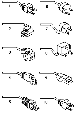
Ten power cord plug types, numbered 1 to 10 to match the Ref. column of the power cord table

Warning: Use the power cord certified for your country.

Index Country FRU No.
1 Colombia, U.S., Venezuela 13F9959
1 Japan, 2-pin 6454377
1 Japan, 3-pin 65F0031
2 Hong Kong, Singapore, U.K. 14F0033
3 France, Germany, Spain 13F9979
4 Italy 14F0069
5 Australia, New Zealand 13F9940
6 Denmark 13F9997
7 Israel 14F0087
8 Bangladesh, Pakistan, Sri Lanka, South Africa 14F0015
9 Switzerland 14F0051
10 Thailand 1838574

Safety Notice 8 #

Warning Safety Notice 8

Before removing any FRU, power-off the computer, unplug all power cords from electrical outlets, remove the battery pack, then disconnect any interconnecting cables.

Avant de retirer une unité remplaçable en clientèle, mettez le système hors tension, débranchez tous les cordons d'alimentation des socles de prise de courant, retirez la batterie et déconnectez tous les cordons d'interface.

Die Stromzufuhr muß abgeschaltet, alle Stromkabel aus der Steckdose gezogen, der Akku entfernt und alle Verbindungskabel abgenommen sein, bevor eine FRU entfernt wird.

Prima di rimuovere qualsiasi FRU, spegnere il sistema, scollegare dalle prese elettriche tutti i cavi di alimentazione, rimuovere la batteria e poi scollegare i cavi di interconnessione.

Antes de quitar una FRU, apague el sistema, desenchufe todos los cables de las tomas de corriente eléctrica, quite la batería y, a continuación, desconecte cualquier cable de conexión entre dispositivos.

Safety Notice 1 #

Warning Safety Notice 1

Before the computer is powered-on after FRU replacement, make sure all screws, springs, or other small parts are in place and are not left loose inside the computer. Verify this by shaking the computer and listening for rattling sounds. Metallic parts or metal flakes can cause electrical shorts.

Avant de remettre l'ordinateur sous tension après remplacement d'une unité en clientèle, vérifiez que tous les ressorts, vis et autres pièces sont bien en place et bien fixées. Pour ce faire, secouez l'unité et assurez-vous qu'aucun bruit suspect ne se produit. Des pièces métalliques ou des copeaux de métal pourraient causer un court-circuit.

Bevor nach einem FRU-Austausch der Computer wieder angeschlossen wird, muß sichergestellt werden, daß keine Schrauben, Federn oder andere Kleinteile fehlen oder im Gehäuse vergessen wurden. Der Computer muß geschüttelt und auf Klappergeräusche geprüft werden. Metallteile oder -splitter können Kurzschlüsse erzeugen.

Prima di accendere l'elaboratore dopo che é stata effettuata la sostituzione di una FRU, accertarsi che tutte le viti, le molle e tutte le altri parti di piccole dimensioni siano nella corretta posizione e non siano sparse all'interno dell'elaboratore. Verificare ciò scuotendo l'elaboratore e prestando attenzione ad eventuali rumori; eventuali parti o pezzetti metallici possono provocare cortocircuiti pericolosi.

Antes de encender el sistema despues de sustituir una FRU, compruebe que todos los tornillos, muelles y demás piezas pequeñas se encuentran en su sitio y no se encuentran sueltas dentro del sistema. Compruébelo agitando el sistema y escuchando los posibles ruidos que provocarían. Las piezas metálicas pueden causar cortocircuitos eléctricos.