ThinkPad Laptops

ThinkPad 510Cs

Machine Type 2604 · 1994 · 30 sections

IBM's 1994 colour subnotebook, with a 7.7-inch colour screen, a 50 MHz 486BL2 processor and a 200MB hard disk in a 4-pound case. It has no internal diskette drive: an external drive and cable came in the box, with the ThinkPad MultiPort port replicator.

This transcribed historical service reference may contain incomplete captures. The linked original manuals remain authoritative.

Service Reference

Product Overview #

Compiled from a hardware survey and IBM's product records. A dash means no source records the value.

ThinkPad 510CS specifications
Specification ThinkPad 510CS
Released June 1994
Processor IBM 486BL2, 50 MHz (soldered QFP package)
Chipset Western Digital WD8110LV
Bus AT bus
Memory Standard 4 MB; maximum 20 MB; IC DRAM card
CMOS RAM 256 bytes
Storage 2.5" IDE: 200 MB
Display 7.7" passive matrix colour, 640 × 480
Graphics Western Digital WD90C24A2, 1 MB video memory
Audio PC speaker
Main battery NiMH
CMOS battery Soldered lithium coin cell
Power connector Barrel jack
Media drives None; external floppy drive supported
PC Card slots
  • 1 × PCMCIA (Type II)
  • Ricoh RF5C366C controller
Networking None
Ports
  • Parallel
  • Port replicator connector
  • External floppy connector
BIOS Phoenix BIOS
Pointing device TrackPoint
IBM model codes — 3 models of machine type 2604
VariantModel codes
Variant not recorded2604-C2A, 2604-C2C, 2604-C2U

Status Indicators #

Source: Hardware Maintenance Manual Volume 1: Laptop, Notebook, Portable and ThinkPad Computers, p.280

IBM's table pairs a symbol for each indicator with its meaning. The symbols are drawn on PDF page 280 of the Hardware Maintenance Manual, Volume 1; in the manual's order, the indicators show:

  • Battery needs charging
  • Battery is charging
  • Computer is powered-on
  • Computer is in suspend mode
  • Hard disk drive is active
  • Diskette drive is active
  • Keyboard is in Num Lock mode
  • Keyboard is in Caps Lock mode
  • Keyboard is in Scroll Lock mode

General Checkout #

Source: Hardware Maintenance Manual Volume 1: Laptop, Notebook, Portable and ThinkPad Computers, p.270

Start here. IBM's entry procedure for the ThinkPad 510: run the Power-On Self Test or the Advanced Diagnostics, then use the symptom table at the end to pick the next procedure.

Attention Important

The Advanced Diagnostics program is shipped on the hard disk drive. An external diskette drive must be attached to the computer to run the diagnostics program from a diskette. The Advanced Diagnostics diskette, part number S83G8095, contains the same Advanced Diagnostics program shipped on the hard disk drive. If the diagnostics are not on the hard disk drive and an external diskette drive is not attached to the computer, do the following.

  1. Run the POST (Power-On Self Test).
  2. If you receive an error, go to Symptom-to-FRU Index.
  3. If you suspect an undetermined problem, go to Undetermined Problems.
  1. Power-off the computer and all external devices.
  2. Check all cables and power cords for correct connection.
  3. If you are going to run the advanced diagnostics from the diskette drive; insert the Advanced Diagnostics diskette into the diskette drive, then continue with step 4.

    If you are going to run advanced diagnostics from the hard disk drive, go to step 6.

  4. Power-on all external devices.
  5. Power-on the computer and check for one short beep at the end of POST with a clear and readable diagnostics menu displayed.

    If you did not get the correct responses, go to Symptom-to-FRU Index.

    If you received the correct responses, go to step 12.

  6. Power-on all external devices.
  7. Power-on the computer and check for one short beep at the end of POST with a clear and readable diagnostics menu displayed. If you did not get the correct responses, go to Symptom-to-FRU Index.

    Note: The following two steps are important because they prevent programs which might affect the diagnostic tests from being loaded into memory.

  8. When the message Starting PC DOS appears, press F5.
  9. When the DOS prompt appears, type cd c:\thinkpad\diags
  10. Press Enter.
  11. Type command
  12. Press Enter to start the advanced diagnostics; then, continue with the next step.
  13. Run the advanced diagnostics tests. For information on how to disable the password, see Power-On Password Override.
  14. Find your symptom below, then go to the appropriate page. Otherwise, see Symptom-to-FRU Index, then go to Undetermined Problems.
Symptom Go to ...
Error Code or Message Symptom-to-FRU Index
Configuration Problem Checking the Installed Devices List
Power Problem Power Systems Checkout
Memory Problem Memory Checkout
TrackPoint II Problem TrackPoint II Checkout

Note: For information about diagnostics, error messages, passwords, and other tests and service checks, go to Related Service Procedures.

TrackPoint II Checkout #

Source: Hardware Maintenance Manual Volume 1: Laptop, Notebook, Portable and ThinkPad Computers, p.482

  • If the TrackPoint II does not work, check the configuration. If the configuration of the TrackPoint II is set to Disabled or Off, change it to Enable or On.

    If the problem remains, continue.

    Note: TrackPoint II automatically compensates to adjust the pointer sensor. This causes the pointer to move slightly on the screen and then stop. Pointer movement might occur when a slight, steady pressure is applied to the TrackPoint II pointer when the computer is powered-on or running, or when exceeded temperature range requires re-adjustment.

  • If the cursor floats or moves erratically, power-off and disconnect the mouse. Power-on the computer. If the problem goes away, replace the mouse. If the problem remains, replace the keyboard.
  • For click button or pointing stick problems:

    1. Go to the Easy-Setup screen.
    2. Select an item with the pointing stick.
    3. Press either left or right click button.
    4. Verify that both buttons work correctly.

    If the pointing stick or the click button does not work, do the following.

    1. Reseat the keyboard cables.
    2. Replace the keyboard.
    3. Replace the interposer card (355x, 360x, 750x, 755x).
    4. Replace keyboard control card (720).
    5. Replace the system board.

Memory Checkout #

Source: Hardware Maintenance Manual Volume 1: Laptop, Notebook, Portable and ThinkPad Computers, p.272

001
  • Always start with General Checkout.
  • Power-off (O) the computer and wait 10 seconds.
  • Reseat the DRAM card.
  • Run the advanced diagnostics; if necessary refer to Loading the Diagnostics.
  • Make a note of any error code you receive.

DID YOU RECEIVE A 20X XXXXXXXX XXXXXXXX OR 02XX POST ERROR OR FAILURE SYMPTOM?

Yes — go to Step 003. No — go to Step 002.

002

Go to Step 006.

003

IS A DRAM CARD INSTALLED?

Yes — go to Step 005. No — go to Step 004.

004

Replace the system board. Press Ctrl+Alt+F3 to set the time and date to remove the 16X errors.

005

Replace the DRAM card.

If the error remains, replace the system board. Press Ctrl+Alt+F3 after POST to set the time and date and remove the 16X errors.

006

(From step 002)

  • If you need to bypass an error, press Esc or F1.
  • If you cannot continue, you might have a keyboard problem; go to Symptom-to-FRU Index.

DID THE ADVANCED DIAGNOSTICS MENU APPEAR?

Yes — go to Step 008. No — go to Step 007.

007

You might have a diskette drive problem; go to Symptom-to-FRU Index.

008
  • Press 0 (SYSTEM CHECKOUT), then press Enter.
  • Follow the screen instructions.

Note: Ignore a 199 error.

  • Press 0 (RUN TESTS ONE TIME), then press Enter.
  • Press 2 (MEMORY), then press Enter.

DID YOU RECEIVE A 2XX ERROR OR FAILURE SYMPTOM?

Yes — go to Step 010. No — go to Step 009.

009

Go to Step 011.

010

Go to Step 003.

011

(From step 009)

DID THE SYSTEM CHECKOUT MENU APPEAR AT THE END OF TEST?

Yes — go to Step 013. No — go to Step 012.

012

You might have a power source problem; go to Power Systems Checkout.

013

The advanced diagnostics tests finished without detecting a failure. If you suspect an intermittent problem, start an error log. If you need instructions, refer to Error Log.

PCMCIA Test Card #

Source: Hardware Maintenance Manual Volume 1: Laptop, Notebook, Portable and ThinkPad Computers, p.280

The green LED on the PCMCIA test card lights when the PCMCIA test is running. If the LED does not go on, check that the card is installed correctly by reseating the card. (For the docking station, if it still does not light after reseating, try using another slot for the test.) If the LED still does not go on and the test fails, replace the FRU shown in the diagnostic error code.

Checking the Installed Devices List #

Source: Hardware Maintenance Manual Volume 1: Laptop, Notebook, Portable and ThinkPad Computers, p.281

If an adapter or device is missing from the Installed Devices list and you are able to add it to the list, do so and continue with the diagnostic tests.

If an adapter or device is missing from the installed devices list and you cannot add it to the list, you might have one of the following conditions:

  • The diagnostic code for the missing device is not on your Advanced Diagnostics diskette.
  • The missing device is a 3.5-Inch External Diskette Drive Adapter, or another unrecognizable adapter.
  • The missing device is defective.
  • The adapter or device is not an IBM product.

If the number of drives installed in the computer differs from the number shown in the installed devices list, an error can occur during the diagnostic tests. Restart the computer and correct the drive information in the Set Configuration menu before running the diagnostic tests.

Power Systems Checkout #

Source: Hardware Maintenance Manual Volume 1: Laptop, Notebook, Portable and ThinkPad Computers, p.274

To check the system power, do the following.

  1. Power-off the computer.
  2. Remove the battery from the computer.
  3. Check the battery voltage. The voltage should be a minimum of 10.8 V dc.

    If the voltage is not correct, try recharging the battery pack.

    If the voltage is correct, continue with the next step to test the AC adapter voltage.

  4. Unplug the AC adapter from the computer.
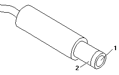
  5. Measure the voltage at the points shown.

    Plug of the AC adapter cable with measuring points 1 and 2 labelled

    V dc + Lead − Lead
    +16.6 2 1

    If the voltage is not correct, replace the AC adapter.

    If the voltage is correct, go to Undetermined Problems.

Power Management Features #

Source: Hardware Maintenance Manual Volume 1: Laptop, Notebook, Portable and ThinkPad Computers, p.275

Press Func+F3 to select Power Management setup (any time after the computer is powered-on).

Attention Important

Before using the power saving features, be sure to read and observe the following precautions:

  • If you enter Suspend or Hibernate mode with a diskette inserted in the diskette drive, the same diskette must be installed in the drive before attempting to resume normal operation.
  • If you enter Suspend or Hibernate mode with a PCMCIA card inserted in the PCMCIA slot, the same PCMCIA card must be installed in the slot before attempting to resume normal operation.

    Hibernate mode does not save/restore the status of PCMCIA cards. When you resume normal operation from Hibernate mode, the PCMCIA card is no longer configured and will not be recognized by the computer.

  • If the computer is connected to a Local Area Network (LAN) that periodically polls for station activity, the LAN-connection might be terminated while the computer is in Suspend or Hibernate mode. Any further attempt to access the network results in a brief delay and the computer appears to hang (up to 1 minute, depending on the network). After the delay, an error is displayed. Follow the instructions on the screen to restore normal operation.
  • Any software program that was running over the LAN is not re-entered when you resume normal operation from Hibernate or Suspend modes.

Loading the Diagnostics #

Source: Hardware Maintenance Manual Volume 1: Laptop, Notebook, Portable and ThinkPad Computers, p.282

To start advanced diagnostics from the Advanced Diagnostics diskette, do the following.

  1. Insert the Advanced Diagnostics diskette into the diskette drive.
  2. Power-on all external devices.
  3. Power-on the computer. (The advanced diagnostics program will load from the diskette drive.)

To start advanced diagnostics from the hard disk drive, do the following.

  1. Power-on all external devices.
  2. Power-on the computer.

    Note: Some programs cause the diagnostic tests to give inaccurate results. The following steps prevent these programs from being loaded into memory while starting the advanced diagnostics.

  3. When the message Starting PC DOS appears, press F5.
  4. When the DOS prompt appears, type cd c:\thinkpad\diags
  5. Press Enter.
  6. Type command
  7. Press Enter to start the advanced diagnostics program.

Accessing the Diagnostic Tests

To access diagnostic tests from the SELECT AN OPTION Menu, do the following.

  1. Select 0 (SYSTEM CHECKOUT), then press Enter.
  2. At the Installed Devices menu, press (Y), then press Enter.
  3. The SYSTEM CHECKOUT menu is then displayed.
  4. Select 0 or 1 from the SYSTEM CHECKOUT menu.
  5. Select the device to be tested.

Power-On Self Test (POST) #

Source: Hardware Maintenance Manual Volume 1: Laptop, Notebook, Portable and ThinkPad Computers, p.281

Each time you power-on the computer, the POST is initiated. The POST takes up to 15 seconds to complete, depending on the options installed.

The POST checks the following: system board, memory, display, keyboard, hard disk drive, parallel port, and serial port.

To start the POST, power-on the computer. You hear one short beep when the POST successfully ends.

If the POST cannot be completed successfully, an invalid configuration error message appears. If F1 is pressed, the system bypasses the error and attempts to complete POST. Press F1 to continue or Press F2 to go to Setup.

External Display Self-Test #

Source: Hardware Maintenance Manual Volume 1: Laptop, Notebook, Portable and ThinkPad Computers, p.476

If the display problem occurs only when using an external display, use the following instructions to correct the problem.

Note: Before you replace a display, check the following list to see if it is connected correctly.

  • 8506 and 8508 displays must be connected to an Image Adapter/A or an Image-I Adapter/A.
  • 63XX and 85XX systems support either 63XX or 85XX displays.
  • 85XX systems with an XGA-2 adapter support 95XX displays.
  • 95XX systems support either 63XX, 85XX, or 95XX displays.
  • ThinkPad models support either 85XX or 95XX displays.

If the screen is rolling, replace the display assembly. If that does not correct the problem, replace FRUs in the following order until the problem goes away:

  1. Video card
  2. Display adapter (any type)
  3. System board
  4. Bus adapter (if used)

If the screen is not rolling, run the display self-test as follows:

  1. Power-off the computer and display.
  2. Disconnect the display signal cable.
  3. Power-on the display.
  4. Set the contrast to its maximum position.
  5. Set the brightness control to the center detent position.

Check for the following conditions:

  • You should be able to vary the screen intensity by adjusting the contrast and brightness controls.
  • The screen should be white or light gray, with a black margin (test margin) on the screen.

    Note: The location of the test margin varies with the type of display. The test margin might be on the top, bottom, or one or both sides.

If you do not see a test margin on the screen, replace the display. If there is a test margin on the screen, replace the system board.

Note: On ThinkPad Models 700, 700C, 720C, 720C, do the following:

  1. Video card
  2. System board

Symptom-to-FRU Index #

Source: Hardware Maintenance Manual Volume 1: Laptop, Notebook, Portable and ThinkPad Computers, p.276

On this page IBM's index continues in separate sections: Numeric Error Codes, Beep Symptoms, Miscellaneous Symptoms and Undetermined Problems.

The Symptom-to-FRU Index lists symptoms, errors, and the possible causes. The most likely cause is listed first. Use this index to help you decide which FRUs to have available when servicing the computer.

In the following error codes, X can be any number.

Note: For IBM devices not supported by the ThinkPad diagnostic code, refer to the manual for that device.

Miscellaneous Symptoms #

Source: Hardware Maintenance Manual Volume 1: Laptop, Notebook, Portable and ThinkPad Computers, p.277

Symptom/Error FRU/Action
Blank screen
  1. Battery
  2. AC Adapter
  3. DRAM Card
  4. System Board
Display problems (For external displays, see External Display Self-Test before replacing FRUs.)
  1. External Display, if installed
  2. External Display Power Cord
  3. LCD Assembly
  4. System Board
LCD contrast not adjustable
  1. LCD Assembly
  2. System Board
Keyboard problems
  1. Reseat cables
  2. Keyboard
  3. System Board
Mouse problems
  1. Reseat cable
  2. Mouse
  3. System Board
Diagnostic tests hang
  1. Battery
  2. AC Adapter
  3. DRAM Card
  4. System Board
Blinking cursor only
  1. Diskette Drive
  2. System Board
Diskette drive bypassed
  1. Reseat DASD/Serial Cable
  2. ThinkPad MultiPort
  3. Diskette Drive
Cannot read diskette
  1. Diskette Drive
  2. Diskette Drive Cable
  3. Diskette
  4. System Board
Hard disk drive problem
  1. Hard Disk Drive
  2. Hard Disk Drive Cable
  3. System Board
Printer problem
  1. Check Configuration
  2. ThinkPad MultiPort
  3. Parallel Port
  4. System Board
Communication or plotter problem
  1. Check Configuration
  2. ThinkPad MultiPort
  3. Serial Port
  4. PCMCIA Device
  5. System Board

Undetermined Problems #

Source: Hardware Maintenance Manual Volume 1: Laptop, Notebook, Portable and ThinkPad Computers, p.279

If you have not already done so, go to Power Systems Checkout and check the AC adapter and battery voltages.

If the AC adapter and battery voltages are correct and the problem remains, do the following.

  1. Power-off the computer.
  2. Remove or disconnect one of the following devices:
    • Any external device or cable
    • Any PCMCIA device
  3. Power-on the computer.
  4. If the symptom remains, repeat steps 1, 2, and 3 until you find the failing adapter or device.
  5. If the problem remains, replace the Power Card.
  6. If this does not solve the problem, replace the system board.

Formatting the Hard Disk Drive #

Source: Hardware Maintenance Manual Volume 1: Laptop, Notebook, Portable and ThinkPad Computers, p.283

Hard disk drives normally contain tracks in excess of their stated capacity to allow for defective tracks. The user is notified by a diagnostic message when the defect limit has been reached and service is recommended.

The Advanced Diagnostics Format program is different from the operating system format program.

Attention Warning

All data on the selected hard disk drive is destroyed during a format operation or surface analysis.

Before the customer can transfer information from the backup diskettes to the hard disk drive, the hard disk drive must be formatted using the operating system format program. Have the customer refer to the operating system manual for a description of the hard disk preparation commands.

After formatting the hard disk drive, copy the System files from the Advanced Diagnostics diskette to the hard disk drive.

Error Log #

Source: Hardware Maintenance Manual Volume 1: Laptop, Notebook, Portable and ThinkPad Computers, p.283

Use the following steps to create an error log, run the diagnostic tests, and automatically record any error messages in an error log. This procedure is normally used to diagnose an intermittent problem.

Note: The errors must be logged to a diskette drive or to a printer. If recording errors on a diskette, use a copy of the Advanced Diagnostics diskette that is not write-protected. Do not run any diskette tests when logging to a diskette drive. Do not run a parallel port test when logging to a printer.

Creating the Error Log

  1. Insert the Advanced Diagnostics diskette into the diskette drive.
  2. Press 0 (SYSTEM CHECKOUT), then press Enter.
  3. Depending on the options installed in the computer, questions about attached devices might appear on the display. Answer as required; then press Enter.
  4. Press Y or N (IS THE LIST CORRECT (Y/N)?), then press Enter.
  5. Press 2 (LOG UTILITIES), then press Enter.
  6. Press 0 (START ERROR LOG), then press Enter.
  7. Press 0 or 1 (LOG TO DISKETTE, OR PRINTER (0/1)?), then press Enter.
  8. If you are logging to diskette, press A (ENTER THE DRIVE ID FOR ERROR LOG?), then press Enter.
  9. Press 9 (END LOG UTILITIES), then press Enter.

Starting the Test

  1. Press 1 (RUN TESTS MULTIPLE TIMES), then press Enter.
  2. Select the device you suspect has a failure, then press Enter.
  3. Select the number of times to run the test; then press Enter.
  4. Press N (WAIT EACH TIME AN ERROR OCCURS (Y/N)?), then press Enter.
  5. Follow any instructions on the display and select all available tests.

    Note: Do not press any keys during the keyboard test.

  6. To end (RUN TEST CONTINUOUSLY), press and hold Ctrl; then press Pause. The computer completes testing and returns to the Installed Devices menu.

Displaying the Error Log

  1. Depending on the options installed in the computer, questions about attached devices might appear on the display. Answer as required; then press Enter.
  2. Press Y or N (IS THE LIST CORRECT (Y/N)?), then press Enter.
  3. Press 2 (LOG UTILITIES), then press Enter.
  4. Press 2 (DISPLAY LOG), then press Enter.
  5. Press A (ENTER THE DRIVE ID FOR ERROR LOG?), then press Enter.
  6. If no errors occurred, the Log Utilities menu appears. If errors are displayed, go to Symptom-to-FRU Index.

Numeric Error Codes #

Source: Hardware Maintenance Manual Volume 1: Laptop, Notebook, Portable and ThinkPad Computers, p.276

Symptom/Error FRU/Action
02X, 101, 107
  1. Battery
  2. AC Adapter
  3. DRAM Card
  4. System Board
102, 103, 104, 106, 108, 109, 190 (Press Ctrl+Alt+F3 to set the time and date and remove any 16X errors.)
  1. System Board
111
  1. DRAM Card
161, 163 (Press Ctrl+Alt+F3 to set the time and date and remove any 16X errors.)
  1. Set Configuration
  2. Battery
  3. System Board
162
  1. Any Device (Check the installed devices list for a missing device.)
  2. System Board
1XX (not listed above)
  1. System Board
2XX
  1. DRAM Card
3XX
  1. Keyboard
  2. System Board
6XX
  1. Diskette Drive
  2. System Board
9XX, 10XX
  1. ThinkPad MultiPort
  2. Any External Parallel Device
  3. System Board
11XX, 12XX
  1. ThinkPad MultiPort
  2. Any External Serial Device
  3. PCMCIA Device
  4. System Board
17XX
  1. Hard Disk Drive
  2. System Board
24XX
  1. ThinkPad MultiPort
  2. LCD/External Display
  3. System Board
80XX
  1. System Board
86XX
  1. Keyboard
  2. System Board

Beep Symptoms #

Source: Hardware Maintenance Manual Volume 1: Laptop, Notebook, Portable and ThinkPad Computers, p.277

Symptom/Error FRU/Action
No beep or continuous beeps (See Power Systems Checkout before replacing any FRUs.)
  1. System Board
  2. DRAM Card
One long and one short beep
  1. DRAM Card
Two long beeps, 3 short beeps, and a blank screen
  1. External Display, if installed
  2. External Display Power Cord
  3. LCD Assembly
  4. System Board
One long beep, 3 long beeps, 3 long beeps and a blank screen
  1. External Display, if installed
  2. External Display Power Cord
  3. LCD Assembly
  4. System Board
Multiple short beeps
  1. Keyboard (stuck key)
One short beep with a display problem (For external displays, see External Display Self-Test before replacing FRUs.)
  1. External Display
  2. Display Power Cord
  3. LCD Assembly
One long and multiple short beeps
  1. External Display, if installed
  2. External Display Power Cord
  3. LCD Assembly

FRU Removals and Replacements #

Source: Hardware Maintenance Manual Volume 1: Laptop, Notebook, Portable and ThinkPad Computers, p.288

The exploded view and the bottom-cover screw chart that this procedure refers to are not reproduced on this page; they are on PDF pages 290–291 of the Hardware Maintenance Manual, Volume 1.

Removals and replacements

Follow the list below for the sequential removal of FRUs. See the illustration on ThinkPad 510 Exploded View for locations and identification of FRUs. The letters in parentheses in the list indicate screw types. See Bottom Cover Screws to match the letters to the correct screw type and size before replacing each screw.

Safety Notice 8

Before removing any FRU, power-off the computer, unplug all power cords from electrical outlets, remove the battery pack, then disconnect any interconnecting cables.

Safety Notice 1

Before the computer is powered-on after FRU replacement, make sure all screws, springs, or other small parts are in place and are not left loose inside the computer. Verify this by shaking the computer and listening for rattling sounds. Metallic parts or metal flakes can cause electrical shorts.

  1. Remove Battery Pack
  2. Lift Keyboard

    (Tabs located along the inside front edge of the keyboard hold the keyboard in the bottom cover. Insert a small screwdriver at 2A and 2B, between the front of the keyboard and the bottom cover. Gently pry the bottom cover away from the keyboard to release the keyboard.)

  3. Disconnect Three Ribbon Cables

    Remove Keyboard

    Attention CAUTION: Be careful not to scratch the LEDs or LCD display when removing the keyboard

    (If you are removing the system board, disconnect all flat cables. Slide each connector latch retainer away from the base to release each cable.)

  4. Disconnect Hard Disk Drive Ribbon Cable

    (Disconnect the cable at the system board connector.)

  5. Remove Bottom Cover Screws

    See Bottom Cover Screws.

    • (2-G screws near mouse buttons)
    • (1-EE screw in center)
    • (2-DD screws between the right mouse button and the PCMCIA slot)
    • (5-EE screws around bottom cover perimeter)
  6. Remove Bottom Cover (with Hard Disk Drive and Cable Attached)

    Attention CAUTION: When removing the bottom cover, be careful not to damage the PCMCIA test card.

    (Slide the bottom cover past the PCMCIA eject button as you lift the cover off.)

    (If you are not removing the hard disk drive, go to step 9.)

  7. Disconnect Hard Disk Drive Ribbon Cable

    (Disconnect the cable from the hard disk drive.)

  8. Remove the Hard Disk Drive

    (4-G screws near FCC notice)

  9. Lift System Board

    (Gently lift the system board and turn it over. Be careful not to lose the two plastic system board inserts.)

  10. Disconnect Pointing Device Cable
  11. Disconnect LCD Display Cable
  12. Disconnect Parallel Port Cable

    (In metal frame on system board rear)

    Power Switch Assembly, see Parts Listing.

  13. Remove Two Threaded Power Card Spacers
  14. Remove Power Card
  15. Remove Mouse Buttons

Locations #

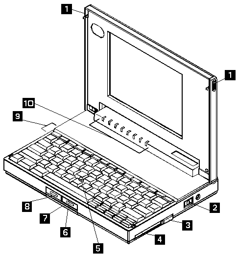
ThinkPad 510 with the display open, showing the controls and features numbered 1 to 10

  1. Top Cover Release Latches
  2. On/Off Switch
  3. PCMCIA Eject Button
  4. PCMCIA Slot
  5. TrackPoint II
  6. Right Button (pointing stick)
  7. Memory Card Access Panel
  8. Left Button (pointing stick)
  9. Battery
  10. Status Indicator LEDs

Power-On Password Override #

Source: Hardware Maintenance Manual Volume 1: Laptop, Notebook, Portable and ThinkPad Computers, p.280

Passwords

To override a password, do the following.

  1. Power-off the computer.
  2. Disconnect all cables attached to the computer.
  3. Remove the memory card access panel and DRAM card (if installed).
  4. Power-on the computer.
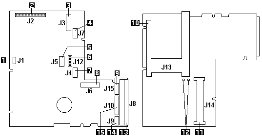
  5. Locate the two pins labeled PAD1-2 on the system board (see System Board Connectors).
  6. Short the two pins together.
  7. Press Ctrl+Alt+F3 to access the System Parameters Setup Menu.
  8. Press Esc.
  9. Press F5 to reset the parameter to their default values.
  10. The System Time, System Date, and Password (if required) parameters need to be set manually.
  11. Press Esc, then F4 to save the values, exit the Setup program, and reboot the computer.
  12. If a DRAM card was removed, power-off the computer and install the DRAM card.
  13. Install the memory card access panel.

Restoring the TP 510 System Files #

Source: Hardware Maintenance Manual Volume 1: Laptop, Notebook, Portable and ThinkPad Computers, p.283

The subdirectory C:\THINKPAD\DIAGS on the hard disk drive contains the ThinkPad 510 Diagnostics programs.

If the hard disk drive is reformatted or the files in the subdirectory on the hard disk drive are corrupted, use the Advanced Diagnostics diskette to restore the diagnostic programs.

Attention Important

The following is required to complete this procedure:

  • DOS must be installed on the hard disk drive.
  • An external diskette drive must be attached to the computer.
  1. Power-on the computer; then, insert the Advanced Diagnostics diskette.
  2. At the DOS prompt, type A:UINSTALL then press Enter.
  3. Select Install ThinkPad 510 Diagnostics from the menu. The files are copied from the diskette to the THINKPAD\DIAGS subdirectory on drive C.

Utilities #

The system is configured with several utility programs. These programs provide added function that enhances the usability of the system. These programs should be backed up to prevent loss of data. Use the Diskette factory in Microsoft Windows to make a backup copy of the Advanced Diagnostics diskette. The utility programs are:

SIMUL

Allows you to enable/disable simultaneous display on both the LCD and external monitor.

Note: The computer does not enter Suspend/Resume while in the Simultaneous mode. You must exit Simultaneous mode before Suspend/Resume is allowed. Also, the Func + F7 function is not recognized until you exit the Simultaneous mode.

EPP2
Provides Enhanced Parallel Port Utility. This utility needs to be added to the AUTOEXEC.BAT and CONFIG.SYS if the option attached to the parallel port supports the enhanced parallel port mode.
PHDISK

Prepares the hard disk drive for the hibernation feature, including formatting and the marking of defective areas. A partition is reserved on the hard disk drive to save data before the computer enters Hibernation mode.

Attention Warning: Running this utility causes loss of data on the hard disk drive. It is important that the customer backup all data prior to using this utility.

Important

Run the PHDISK utility if you change the operating environment, reformat the hard disk drive, or add additional memory.

PCMCIA Drivers
IBM2SS01.SYS and PCMCIA.SYS provide the ability to use PCMCIA cards in an OS/2 environment.

Parts Listing #

Source: Hardware Maintenance Manual Volume 1: Laptop, Notebook, Portable and ThinkPad Computers, p.294

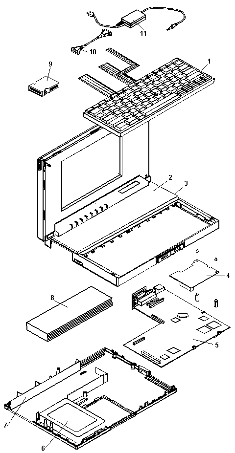
Exploded view of the ThinkPad 510 with parts numbered 1 to 11, including the keyboard, LCD, system board, hard disk, battery and AC adapter

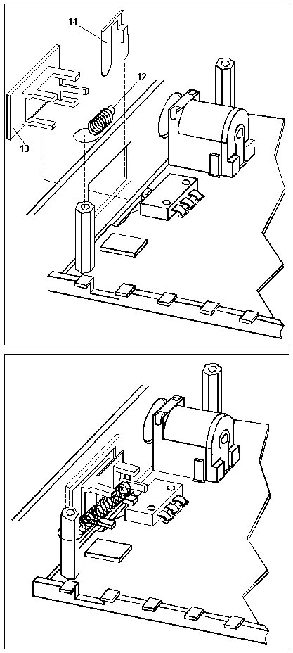
Power switch assembly detail: the power switch spring (12), slide (13) and clip (14), shown apart and installed

ThinkPad 510 System Unit FRUs
Index Description FRU No.
1 Keyboard Assembly (US English) 73G3394
1 TrackPoint II Cap Set 73G3463
2 Color LCD Assembly 73G3387
3 Power Switch Assembly (See Index numbers 12, 13 and 14.)
4 Power Card 73G3465
5 System Board 88G1121
5 System Board Bracket 73G3391
6 200MB Hard Disk 73G3443
7 Base Cover Assembly 73G3395
7 Connector Door 73G3420
8 Rechargeable Battery 73G3417
9 ThinkPad MultiPort 73G3388
10 Diskette Drive Cable (External) 73G3422
10 Parallel Port Cable (Internal) 73G3421
10 Hard Disk Cable (Internal) 59G7927
11 AC Adapter 73G3411
12 Power Switch Spring 73G3449
13 Power Switch Slide 73G3385
14 Power Switch Clip 73G3448
– 4MB IC DRAM 8189098
– 8MB IC DRAM 8189099
– 16MB IC DRAM 19H8061
– External Diskette Drive 59G7918
– Screw Pack
  • 1 mouse/hard disk drive screw
  • 1 system board insert screw
  • 1 bottom cover screw
  • 1 power card standoff
  • 1 parallel stud
  • 1 plastic system board insert
73G3445