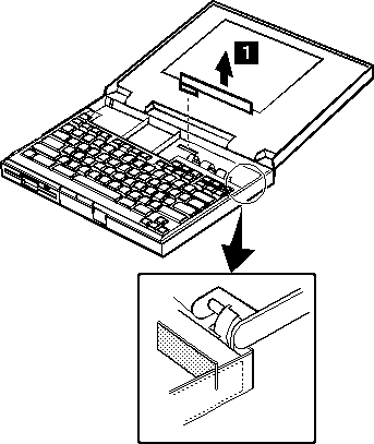
ThinkPad Laptops

ThinkPad 340 / 345

Machine Type 2610 · 1994–95 · 70 sections

IBM's affordable 486 notebooks of 1994–95, built around an IBM 486SLC2 processor: the ThinkPad 340 has a 9.4-inch monochrome screen and the 340CSE a 9.4- or 10.4-inch colour one. The service procedures here come from IBM's Hardware Maintenance Manual for the 340 and 340CSE.

This transcribed historical service reference may contain incomplete captures. The linked original manuals remain authoritative.

Service Reference

Product Overview #

Four variants side by side, compiled from a hardware survey and IBM's product records. A value spanning several columns applies to each of those variants; a dash means no source records it.

Specifications by variant
Specification ThinkPad 340 ThinkPad 340CSE ThinkPad 345CS ThinkPad 345C
Released September 1994 February 1995 September 1995
Processor IBM 486SLC2, 50 MHz (soldered QFP package) IBM 486SLC2, 50 or 66 MHz (soldered QFP package) Intel 486DX4, 75 MHz
Chipset PicoPower Cypress (PT86C366) —
Memory Standard 4 MB; maximum 12 MB; IC DRAM card Standard 4 MB; maximum 20 MB; IC DRAM card
CMOS RAM 128 bytes —
Storage 2.5" IDE; no drive adapter required 2.5" IDE: 200 or 360 MB; no drive adapter required 2.5" IDE: 360 or 540 MB; no drive adapter required
Display 9.4" passive matrix greyscale, 640 × 480
  • 9.4" passive matrix colour, 640 × 480
  • 10.4" passive matrix colour, 640 × 480
10.4" passive matrix colour, 640 × 480 10.4" active matrix, 640 × 480
Graphics OPTi 92C168, 512 KB video memory Western Digital WD90C24A, 1 MB video memory
Audio PC speaker
Main battery NiMH
CMOS battery NiCad
Power connector Barrel jack
Media drives 3.5" 1.44 MB floppy drive
PC Card slots 1 × PCMCIA (Type III)
Networking None
Ports
  • Parallel
  • Serial
  • VGA out
  • PS/2
BIOS IBM BIOS with Easy-Setup
Pointing device TrackPoint
IBM model codes — 8 models of machine type 2610
VariantModel codes
ThinkPad 340CSE2610-23D, 2610-2CD, 2610-2ED, 2610-2JD, 2610-2YD, 2610-2ZD, 2610-DS1, 2610-J3D

Status Indicators #

Source: Hardware Maintenance Manual Volume 2: ThinkPad Computers, p.54

The system status indicators show the current computer status in different colors (green, yellow, and orange).

Symbol Color Meaning
Battery status indicator Green Battery is fully charged.
Yellow (340)

Battery usable. Battery is charging (when the AC Adapter is used).

Note: When the battery is fully charged, the indicator turns and stays green.

Orange Battery is low
Blinking orange Battery is almost depleted
Blinking yellow (340)

Battery cannot be charged because of it's high temperature.

Note: When the temperature drops to the acceptable range, charging will start.

Off (340CSE) The battery in not installed.
Diskette drive in-use indicator Orange Diskette drive is in-use
Hard disk drive in-use indicator Orange Hard disk drive in-use
Num Lock indicator Green Keyboard is in Num Lock mode
Caps Lock indicator Green Keyboard is in Caps Lock mode
Scroll Lock indicator Green Keyboard is in Scroll Lock mode
Power-on indicator Green Computer is powered on

Fn Key Combinations #

Source: Hardware Maintenance Manual Volume 2: ThinkPad Computers, p.57

The following table shows the Fn key and function key combinations and their corresponding functions.

The Fn key works independently from the operating system. The operating system obtains the status through the system management interface to control the system.

Fn + Description
F1 Reserved
F2 Fuel-gauge display ON/OFF
F3 Standby mode invocation
F4 Suspend mode invocation
F5 Audio volume Down
F6 Audio volume UP
F7 LCD/CRT display switching
F8 LCD normal/reverse switching
F9 Reserved
F10 Reserved
F11 Power management mode switching (Toggles High power, Medium, Low)
F12 Reserved

Using the Function Key #

This is the Function key on the front panel of the optional TV Tuner, not the keyboard Fn key; see TV Tuner for the other controls. In the table, <- and +> stand for the Down and Up switches.

Each time you press the Function key (Fn key), one of the following messages (called On-Screen Message) appears at the top left corner of the LCD.

The changed values are automatically saved when you return to the “TV Channel” On-Screen message. The values are not saved when you power-off the TV Tuner without returning to this message.

Message on LCD Parameter
(xx)

TV Channel

By using <- and +>, you can select the channels from 2 to 69.

COL

Color Adjustment

By pressing and holding <- or +>, you can change the color.

TNT

TINT Adjustment

By pressing and holding <- or +>, you can change the tint.

BRT

Bright Adjustment

By pressing and holding <- or +>, you can change the brightness.

CNT

Contrast Adjustment

By pressing and holding <- or +>, you can change the contrast.

---

(No function)

Reserved.

LO
HI

Auto Tune Sensitivity Selection

LO: Means the sensitivity of the TV is low. In this mode, the TV Tuner receives strong TV signals only. To set LO, press <-.

HI: Means the sensitivity of the TV is high (factory default). In this mode, the TV Tuner receives weak and strong TV signals. To set HI, press +>.

D3S
DON

Time On-Screen Message appears

D3S: On-Screen Message appears for 3 seconds. To set D3S, press <-.

DON: On-Screen Message always appears. To set DON press +>.

General Checkout #

Source: Hardware Maintenance Manual Volume 2: ThinkPad Computers, p.35

Use the following procedure as a guide for computer problems. The diagnostic tests are intended to test only IBM products. Non-IBM products, prototype cards, or modified options can give false errors and invalid system responses.

  1. Obtain the failing symptoms in as much detail as possible.
  2. Verify the symptom. Attempt to recreate the failure by running the diagnostic tests or retrying the same operation.

    Note: To run the diagnostics, refer to How to Run the Diagnostics.

  3. Use the following table with the verified symptom to determine which page to go to. Search the symptoms column and find the description that best matches your symptom; then go to the page shown in the “Go to” column.

    Symptom Go to
    Power failure. (The power indicator does not go on or stay on.) Power Systems Checkout.
    POST does not complete. No beeps/error code are indicated. Symptom-to-FRU Index, and then use the No Beep Symptoms table.
    POST beeps, but no error codes are displayed. Symptom-to-FRU Index, and then use the Beep Symptoms table.
    POST detected an error and displayed numeric error codes. Symptom-to-FRU Index, and then use the Numeric Error Codes table.
    The diagnostic test detected an error and displayed an FRU code. FRU Codes.
    The configuration is not the same as the installed devices. Checking the Installed Devices List.
    Other symptoms (such as LCD display problems). Symptom-to-FRU Index, and then use the table for related symptoms.
    Symptoms cannot be recreated. (Intermittent problems.) Use the customer reported symptoms and go to Symptom-to-FRU Index.

Keyboard / Auxiliary Input Device Checkout #

Source: Hardware Maintenance Manual Volume 2: ThinkPad Computers, p.481

Remove the external keyboard if the internal keyboard is to be tested.

If the internal keyboard does not work or an unexpected character appears, make sure that the three flexible cables extending from the keyboard are correctly seated in the connectors on the system board.

If the keyboard cable connection is correct, run the Keyboard Test by doing the following:

  1. Go to advanced diagnostic menu screen by pressing Ctrl+A in the basic diagnostic menu.
  2. Press Ctrl+K; a layout of the keyboard appears on the screen.
  3. Check that when each key is pressed, the key position on the keyboard layout on the screen changes to a black square.

    Notes:

    1. When a Fn key is pressed, a black square briefly appears.
    2. Press the Esc key to return to the diagnostic menu.

If the tests detect a keyboard problem, do the following one at a time to correct the problem. Do not replace a non-defective FRU.

  • Reseat the three cables.
  • Replace the keyboard.
  • Replace the system board.

The following auxiliary input devices are supported for this computer.

  • Numeric keypad
  • Mouse (PS/2 compatible)
  • External keyboard (with keyboard/mouse cable)

If any of the above devices do not work, reseat the cable connector and repeat the failing operation.

If the problem does not occur again, recheck the connector.

If the problem is not corrected, replace the device, and then the system board.

TrackPoint II and III Checkout #

Source: Hardware Maintenance Manual Volume 2: ThinkPad Computers, p.38

If the TrackPoint II or III will not work, check the configuration in Easy-Setup by selecting Keyboard from the Config menu. If the configuration of the TrackPoint II or III is disabled, select TrackPoint to enable it.

If this does not correct the TrackPoint II or III problem, continue with the following.

The TrackPoint II or III does automatic compensations to adjust the pointer sensor. During this process, the pointer moves on the screen automatically for a short time. This self-acting pointer movement can occur when a slight, steady pressure is applied to the TrackPoint II or III pointer while the computer is powered on or while the system is running, or re-adjustment is required because the temperature has exceeded its normal operating range. This symptom does not indicate a hardware problem. No service actions are necessary if the pointer movement stops in a short period of time.

If a click button problem or pointing stick problem occurs, do the following:

  1. Go to the Easy-Setup screen.
  2. Select an item with the pointing stick.
  3. Press either the left or right click button.
  4. Verify that both buttons work correctly.

If either the pointing stick or the click button will not work, do the following actions one at a time to correct the problem. Do not replace a non-defective FRU.

  • Reseat the three keyboard cables.
  • Replace the keyboard.
  • Replace the system board.

Diskette Drive Test #

Source: Hardware Maintenance Manual Volume 2: ThinkPad Computers, p.38

Do the following to isolate the problem to a controller, drive, or diskette. A scratch, write enabled, non-defective 2HD diskette is required.

Note: Make sure that the diskette does not have more than one label attached to it. Multiple labels can cause damage to the drive or can cause the drive to fail.

  1. Do following to select the test device:

    • Select the advanced diagnostic mode and select Tool; then select the icon FDD and press the space key. A √ mark appears next to the selected icon. Insert the blank diskette when instructed.
  2. Run the diskette drive test.
  3. If the controller test detects an error, FRU code 10 appears. Replace the system board.
  4. If the controller test runs without errors, the drive read/write tests start automatically.
  5. If the drive test detects an error, FRU code 50 appears. If the diskette itself is known to be good, replace the drive.

    If no errors occur at the FDD position, the drive is not defective.

PC Test Card LED #

Source: Hardware Maintenance Manual Volume 2: ThinkPad Computers, p.56

The green LED on the PC test card turns on when the PCMCIA test is running. If the LED does not turn on, check that the card is installed correctly by reseating it. If the LED still does not turn on after the card is reseated, try using another slot for the test. If the LED still does not turn on and the test fails, replace the FRU shown in the diagnostic error code.

External Diskette Drive Test #

Source: Hardware Maintenance Manual Volume 2: ThinkPad Computers, p.480

Use the following procedure to isolate the diskette problem to a controller, drive or diskette. A scratch, write-enabled 2HD diskette is required.

  1. Select the icon FDD on the TEST MENU. By doing this, the controller test and the drive read/write test run. If the controller test detects an error, FRU code 10 appears. In this case, replace the system board.
  2. If the controller test run without errors, follow the instructions on the screen and insert a scratch diskette.
  3. If the drive test detects an error, FRU code 50 appears. If the diskette media are known to be good, replace the drive or the drive cable.

External Keyboard / Auxiliary Input Device Checkout #

Source: Hardware Maintenance Manual Volume 2: ThinkPad Computers, p.481

The following auxiliary input devices may be available for IBM ThinkPad models.

  • Numeric keypad
  • Mouse (PS/2 compatible)
  • External keyboard (with Keyboard/Miniature Mouse cable)
  • If you suspect a problem with any of the auxiliary input devices (listed above), replace the device.

    If the problem is not corrected, replace the following FRUs one at a time to correct the problem.

    • Keyboard control card
    • System board
  • If the computer receives an incorrect keyboard response, remove other external devices, check the keyboard connections, and recheck the keyboard responses. If the problem remains, replace the following FRUs one at a time to correct the problem.

    • Keyboard
    • Keyboard control card
    • System board
  • If a 00030100 error message appears, power-off the computer and the external devices. Then power-on the computer before you power-on the external devices.

Fax/Modem Checkout #

Source: Hardware Maintenance Manual Volume 2: ThinkPad Computers, p.482

001
  • Power-off the computer.
  • Ensure that the modem is installed correctly.
  • If the modem never worked in customer mode, ensure that all drivers are loaded correctly onto the computer.
  • Ensure that the communication program is supported on the computer.
  • Ensure that the public switch telephone network (PSTN) cable and the data access arrangement (DAA) cable, if installed, are connected correctly.

If you need to correct one of the above conditions, do so now; then continue.

Note: PCMCIA cards can be inserted and removed while the system is powered on.

  • Power-on the system.
  • Insert the IBM Data/FAX Modem diskette into the default diskette drive.
  • If you are servicing a High Speed Internal Data/Fax Modem (Models FC3632 and FC3650), at the DOS prompt (for example, A:\), type IBMDIAG; then press Enter.
  • If you are servicing a PCMCIA Data/FAX Modem (Models FC3634 and FC3635), at the DOS prompt (for example, A:\), type ESTDIAG; then press Enter.
  • Follow the instructions on the screen. (If you need help, press F1.)

Did the diagnostic tests detect an error?

Yes — go to Step 003. No — go to Step 002.

002

The diagnostic tests have completed successfully. If you suspect a problem, go to Step 004.

003

Go to the Symptom-to-FRU Index for the computer you are servicing.

004
  • Check the PSTN cable and the DAA cable, if installed, for continuity.

Is the cable(s) good?

Yes — go to Step 006. No — go to Step 005.

005

Replace the defective cable(s).

006
  • Have the customer transmit a call.

Was the call transmitted successfully?

Yes — go to Step 008. No — go to Step 007.

007

Go to Step 011.

008
  • Have the customer receive an incoming call on the modem.

Was the incoming call received?

Yes — go to Step 010. No — go to Step 009.

009

Go to Step 014.

010

The diagnostic tests have completed successfully. If you still suspect a problem that is not software related, replace the External DAA; then replace the modem.

011
  • Have the customer transmit a call at a lower speed.

Was the call transmitted successfully?

Yes — go to Step 013. No — go to Step 012.

012

If installed, replace the external DAA. If you do not have an external DAA installed, or replacing the external DAA does not correct the problem, replace the modem.

013

Have the telephone line checked.

014
  • Have the customer receive an incoming call on the modem at a lower speed.

Was the incoming call received?

Yes — go to Step 016. No — go to Step 015.

015

If installed, replace the external DAA. If you do not have an external DAA installed, or replacing the external DAA does not correct the problem, replace the modem.

016

Have the telephone line checked.

Printer Checkout #

Source: Hardware Maintenance Manual Volume 2: ThinkPad Computers, p.484

  1. Make sure the printer is correctly connected and is powered-on.
  2. Run the printer self-test.

If the printer self-test does not run correctly, the problem is in the printer. Refer to the printer service manual.

If the printer self-test runs correctly, do the following.

  1. Verify the port settings in configuration.
  2. Install a wrap plug on the port (indicated in configuration) and run the advanced diagnostic tests.
  3. If the advanced diagnostic tests (with the wrap plug installed) do not detect a failure, replace the printer cable.

    If the problem is not corrected, replace the system board.

Port Replicator Checkout #

Source: Hardware Maintenance Manual Volume 2: ThinkPad Computers, p.485

Use the following procedure to isolate a port replicator problem. A port replicator attaches to the system expansion connector at the rear of the computer.

  1. Power-off the computer.
  2. Remove the failing devices from the replicator.
  3. Unplug the AC adapter from the replicator, if attached.
  4. Remove the port replicator from the computer.
  5. Reconnect the failing device directly to the computer. (If another device occupies the connector, remove it first.)
  6. Go to General Checkout and follow that procedure.
  7. If the advanced diagnostic device test does not find an error, suspect a problem with the port replicator or the system expansion bus.
  8. Power-off the computer and reconnect the port replicator.
  9. Power-on the computer and run the following advanced diagnostic tests:

    • Serial port test with the wrap plug installed on the replicator.
    • Parallel port test with the wrap plug installed on the replicator.
    • PCMCIA-2 test with the PC test card installed.
    • FDD-2 (FDD-1 if no drive is installed in the computer) drive test on the failing device.
  10. If diagnostic errors appear, replace the replicator or diskette drive attachment unit.

    If the problem remains after the replacement, replace the system board.

  11. If power problems appear only when using the replicator, replace the replicator.

If power shut downs occur intermittently when using PCMCIA-2 devices via a port replicator, suspect an over-current problem. Some PCMCIA devices use more power; if the maximum usage of each device occurs simultaneously, the total current will exceed the limit, thereby causing a power shut down. Isolate this problem by removing one of the devices, and use the computer under the same condition, and see whether a power shut down occurs. Do this procedure for all devices then determine the cause. Customer purchase of the larger AC adapter (50W, optional) is recommended, if it is not yet in use.

TrackPoint II Checkout #

Source: Hardware Maintenance Manual Volume 2: ThinkPad Computers, p.486

  • If the TrackPoint II does not work, check the configuration. If the configuration of the TrackPoint II is set to Disabled or Off, change it to Enable or On.

    If the problem remains, continue.

    Note: TrackPoint II automatically compensates to adjust the pointer sensor. This causes the pointer to move slightly on the screen and then stop. Pointer movement might occur when a slight, steady pressure is applied to the TrackPoint II pointer when the computer is powered-on or running, or when exceeded temperature range requires re-adjustment.

  • If the cursor floats or moves erratically, power-off and disconnect the mouse. Power-on the computer. If the problem goes away, replace the mouse. If the problem remains, replace the keyboard.
  • For click button or pointing stick problems:

    1. Go to the Easy-Setup screen.
    2. Select an item with the pointing stick.
    3. Press either left or right click button.
    4. Verify that both buttons work correctly.

    If the pointing stick or the click button does not work, do the following.

    1. Reseat the keyboard cables.
    2. Replace the keyboard.
    3. Replace the interposer card (355x, 360x, 750x, 755x).
    4. Replace keyboard control card (720).
    5. Replace the system board.

Memory Checkout #

Source: Hardware Maintenance Manual Volume 2: ThinkPad Computers, p.36

See the following table for the available memory size of each card.

IC DRAM Memory size
0 MB 3712 KB
2 MB 5760 KB
4 MB 7808 KB
8 MB 11904 KB

Memory errors might stop system operations, show error messages on the screen, or hang the system.

Use the following procedure to isolate memory problems.

Note: Make sure that the memory card is fully installed into the connector. Loose connections can cause errors.

  1. Power-off the computer and remove the IC DRAM card from its slot (if installed).
  2. Press and hold the F1 key; then power-on the computer. Hold the F1 key down until the Easy-Setup screen appears.
  3. Select Test and press Enter.
  4. Select Memory and press Enter to run the memory test on base memory. If an error appears, replace the system board.
  5. Power-off the computer and reinstall the IC DRAM card; then power-on the computer. Verify the memory size; then test the memory. If an error appears, replace the IC DRAM card.

If memory problems occur intermittently, use the loop option to repeat the test. When the test detects an error, an error log is printed on the printer connected to the parallel port. See Error Log for more information.

System Board Checkout #

The processing functions for the computer are performed by the system board. When a numeric code calls out the system board, use the following procedure to isolate the problem.

  1. Run the system board test to verify the symptom. This test verifies the system board. If no error is detected, return to General Checkout.
  2. If FRU code 10 appears, replace the system board.
  3. Rerun the test to verify the fix.

If above procedure does not correct the problem, go to Undetermined Problems.

Checking the Installed Devices List #

Source: Hardware Maintenance Manual Volume 2: ThinkPad Computers, p.56

If a device is installed but the icon appears in a gray shade rather than a dark shade on the basic diagnostics screen, the device is defective. Reseat the device connectors. If the symptom remains, replace the device or the system board. If needed, adjust the contrast control to clearly distinguish the shades of the icon.

If a device that is not installed appears in a dark shade, do the following.

  1. Replace the first device, such as a FDD, HDD, or PCMCIA.
  2. If the problem remains, replace the system board.

PCMCIA, Parallel, and Serial icons are always displayed in dark shade, because the icons represent subsystems of the system board and not attachment of the devices.

Power Systems Checkout #

Source: Hardware Maintenance Manual Volume 2: ThinkPad Computers, p.39

To verify the symptom of the problem, power-on the computer using each of the power sources available as follows.

  1. Remove the battery pack.
  2. Connect the AC Adapter and check that power is supplied.
  3. Disconnect the AC Adapter and install the charged battery pack; then check that power is supplied by battery pack.

If you suspect a power problem, see the appropriate power supply check listed below.

Power Management Features #

Source: Hardware Maintenance Manual Volume 2: ThinkPad Computers, p.43

Two power management modes are provided by the computer to save power consumption and prolong battery power. For the details of the two modes, see the latest volume of the Hardware Maintenance Manual for ThinkPad computers.

Standby Mode: When in standby mode, the following occurs:

  • The LCD backlight turns off.
  • The hard disk motor stops.

Suspend Mode: When in suspend mode, the following occurs:

  • The LCD power is powered-off.
  • The hard disk is powered-off.
  • The CPU is stopped.

Notes:

  1. In the ThinkPad Features Program, the computer can be set to “Will not suspend even if LCD is closed.”
  2. When the computer is powered with ac power and is used with one of the following IBM PC cards, the computer enters standby mode; the PC card and application program remain active.

    • 3270 Emulation Credit Card Adapter
    • 5250 Emulation Credit Card Adapter
    • Token-Ring 16/4 Credit Card Adapter
    • Credit Card Adapter for Ethernet
  3. During the following conditions, the computer cannot enter suspend mode.

    • While the communication link is running.
    • When a serial mouse or other pointing device are selected in the Config menu of Easy-Setup.

Checking the Backup Battery #

  1. Power-off the computer and unplug the AC Adapter from the computer.
  2. Remove the backup battery.
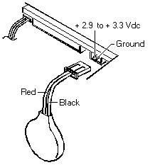
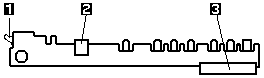
  3. Measure the voltage of the backup battery. See the following figure.

    Backup battery and its connector, with the +2.9 to +3.3 Vdc and ground pins and the red and black wires labelled

    Wire Voltage (V dc)
    Red +2.9 to +3.3
    Black Ground
    • If the voltage is correct, replace the system board.
    • If the voltage is not correct, the backup battery has been discharged. Replace the backup battery.
    • If the backup battery discharges quickly after replacement, replace the system board.

Checking the Battery Pack #

  1. Power-off the computer.
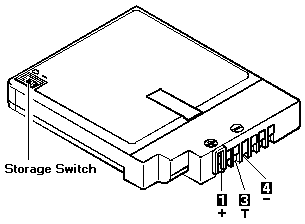
  2. Remove the battery pack and measure the voltage between battery terminals 1 (+) and 4 (-). See the following figure.

    Battery pack showing the storage switch and terminals 1 (+), 3 (T) and 4 (-)

    Terminal Voltage (V dc) / Signal
    340 (NiCd) 340CSE (NiMH)
    1 +10.0 to +18.0 +10.0 to +16.0
    2 NC 0 Ω ground (-)
    3 10 kΩ between ground (-)
    4 Ground (-)
  3. If the voltage is less than +10.0 V dc, the battery pack has been discharged or is defective. Recharge the battery. If the recharging does not work, go to Step 5 to check the charging circuit.

    If the voltage is still less than +10.0 V dc after the recharging, replace the battery.

  4. If the voltage is more than +8.0 V dc, measure the resistance between battery terminals 3 and 4. The resistance must be 4 to 30 kilohms.

    If the resistance is not correct, replace the battery pack.

    If the resistance is correct, replace the system board.

  5. To check the charging circuit, do the following. Plug in the AC Adapter with the battery pack removed; then power-on the computer.
  6. Measure the charging voltage between terminals 1 (+) and 4 (-) on the computer.
  7. If the voltage is less then +10.0 Vdc, replace the system board. If the voltage is more than +10.0 Vdc, the charging circuit is working correctly, replace the battery pack.

Checking the AC Adapter #

You are here because the computer fails only when the AC Adapter is used. If the power-on indicator does not turn on, check the power cord of the AC Adapter for correct continuity and installation.

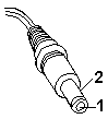
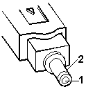
  1. Unplug the AC Adapter cable from the computer and measure the output voltage at the plug of the AC Adapter cable. See the following figure.

    AC Adapter (30W, 40W):

    DC plug of the adapter cable with pins 1 and 2 labelled for measuring the output voltage

    Pin Voltage (V dc)
    1 +17.1 to +18.9
    2 Return

    AC Adapter (35W):

    Plug of the 35 W AC adapter cable with pins 1 and 2 labelled

    Pin Voltage (V dc)
    1 +15.5 to +17.0
    2 Return
    • If the voltage is correct, replace the system board. If the problem is not corrected, go to Undetermined Problems.
    • If the voltage is not correct, go to the next step.
  2. Unplug the AC Adapter cable from the ac power outlet and wait five minutes or longer to allow the protection circuit to be fully discharged and initialized.
  3. Plug the AC Adapter cable into the ac power outlet.
  4. Measure the output voltage of the AC Adapter.
  5. If the voltage is still not correct, replace the AC Adapter.

Note: An audible noise from the AC Adapter does not always indicate a defective adapter.

Checking the Standby Battery #

Warning Be careful not to cause a short circuit when measuring the voltage.
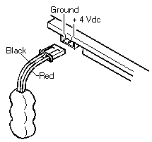
  1. Power-off the computer and unplug the AC Adapter from the computer.
  2. Remove the standby battery.
  3. Measure the voltage of the standby battery.

    • If the voltage between red and black is 3.5 V dc or greater, the voltage is correct. Go to Step 9 to verify standby battery operation.
    • If the voltage is less than 3.5 V dc, go to the next step.
  4. Plug the AC Adapter into the computer and power-on the computer.
  5. Measure the output voltage at the connector on the system board.

    Standby battery connector on the system board with the ground and +4 Vdc pins labelled, beside the battery's black and red wires

    Pin Voltage (V dc)
    + +4.0
    - Ground
    • If the voltage is less than +4.0 V dc, replace the system board.
    • If the voltage is more than +4.0 V dc, power-off the computer, replace the standby battery, and go to the next step.
  6. Ensure that the AC Adapter is plugged into the computer; then power-on the computer.
  7. Charging of the standby battery starts. A depleted battery needs approximately 30 minutes to be recharged to the operational voltage of +3.5 V dc.
  8. Unplug the AC Adapter.
  9. Verify the standby battery function by removing and installing the battery pack during suspend mode.

    Note: Removing and installing the battery pack during suspend mode should be done within one minute.

    The resume operation must start. If the resume operation does not work, switching of power from the battery pack to standby battery will not be correct. Replace the system board.

Power-on the TV Tuner #

Use the ThinkPad Features program or PS2.EXE. to power-on the TV Tuner; then power-on the internal device in the diskette drive compartment.

Attention Warning

If power for the internal device is turned off when the TV Tuner is set up, nothing appears on the LCD display. Turn on power for the TV Tuner again.

  • If you are using DOS, do one of the following:

    • Power-on the computer and type PS2 from the command prompt to start the ThinkPad Features program.

      Select Set Power Features from the ThinkPad Features menu; then put a check mark at Internal Serial Port (or Diskette Drive Compartment) under the Power for devices. If you need help, press F1 to display the help menu.

    • Type PS2 MODEM ON (or PS2 DDC ON) from the command prompt; press the Enter key to set the power ON.
  • If you are using OS/2 or Microsoft Windows, do the following:

    1. Power-on the computer and start the ThinkPad Features program.
    2. Select the Power icon; then move the pointer to Internal Serial Port (or Diskette Drive Compartment) under the Power for devices and click the button to check mark it.
    3. Press the OK button.

How to Run the Diagnostics #

Use either the TrackPoint II or III or the cursor move keys to interact with the tests. The Enter key works the same as selecting the OK icon to reply OK.

  1. Press and hold the F1 key; then power-on the computer. Hold the F1 key down until the Easy-setup screen appears.
  2. Select Test and press Enter.
  3. Select a device and press Enter to run the test.
  4. The test progress screen appears.
  5. OK appears when the test ends without any errors.
  6. Start the Advanced Diagnostic test by pressing Ctrl+A on the basic diagnostic menu screen.
  7. Select Tool to install the tools.
  8. Select a device, press the space key, and install the tool. Multiple devices can be selected by repeating this step.

    A √ mark appears for the selected device.

  9. Select OK and press Enter if the selection is OK.
  10. Select a device and press Enter to start the tests.
  11. Select Test All to test all devices.
  12. Select Loop Test to loop tests.

    A loop option menu appears in which a device loop or all loop can be selected. Select a device and press the space key to select a device. Repeat this step to select multiple devices. Press Enter to start the diagnostic loop. If no device is selected, all device tests are looped.

  13. To exit the loop, keep pressing Ctrl+Pause until the test exits.

How To Run the Keyboard Diagnostics #

Source: Hardware Maintenance Manual Volume 2: ThinkPad Computers, p.57

Do the following to run the keyboard test.

  1. Go to the advanced diagnostic screen menu by pressing Ctrl+A in the Easy-Setup menu.
  2. Go to the keyboard diagnostic test menu by pressing Ctrl+K.
  3. Check that when each key is pressed, the key position on the keyboard layout on the screen changes to a black square.

    Note: When a Fn key is pressed, the black square briefly appears.

External Display Self-Test #

Source: Hardware Maintenance Manual Volume 2: ThinkPad Computers, p.480

If the display problem occurs only when using an external display, use the following instructions to correct the problem.

Note: Before you replace a display, check the following list to see if it is connected correctly.

  • 8506 and 8508 displays must be connected to an Image Adapter/A or an Image-I Adapter/A.
  • 63XX and 85XX systems support either 63XX or 85XX displays.
  • 85XX systems with an XGA-2 adapter support 95XX displays.
  • 95XX systems support either 63XX, 85XX, or 95XX displays.
  • ThinkPad models support either 85XX or 95XX displays.

If the screen is rolling, replace the display assembly. If that does not correct the problem, replace FRUs in the following order until the problem goes away:

  1. Video card
  2. Display adapter (any type)
  3. System board
  4. Bus adapter (if used)

If the screen is not rolling, run the display self-test as follows:

  1. Power-off the computer and display.
  2. Disconnect the display signal cable.
  3. Power-on the display.
  4. Set the contrast to its maximum position.
  5. Set the brightness control to the center detent position.

Check for the following conditions:

  • You should be able to vary the screen intensity by adjusting the contrast and brightness controls.
  • The screen should be white or light gray, with a black margin (test margin) on the screen.

    Note: The location of the test margin varies with the type of display. The test margin might be on the top, bottom, or one or both sides.

If you do not see a test margin on the screen, replace the display. If there is a test margin on the screen, replace the system board.

Note: On ThinkPad Models 700, 700C, 720C, 720C, do the following:

  1. Video card
  2. System board

How to Run the Low Level Format #

Source: Hardware Maintenance Manual Volume 2: ThinkPad Computers, p.56

Do the following to format the hard disk.

Warning Before Formatting the Hard Disk

Make sure that the address of the drive to be formatted is correct. This procedure will erase all information on the disk.

  1. Power-off the computer.
  2. Insert the ThinkPad 750Ce hardware maintenance diskette into diskette drive A and power-on the computer.

    Note: You can use this maintenance diskette for the Model 340CSE.

  3. Select Format the hard disk from the main menu.
  4. Select the drive from the menu.
  5. Follow the instructions on the screen.

Symptom-to-FRU Index #

Source: Hardware Maintenance Manual Volume 2: ThinkPad Computers, p.44

The Symptom-to-FRU Index lists the symptoms, errors, and possible causes. (It can be used to help you decide which FRUs to have available when servicing the computer.) The most likely cause is listed first.

Perform the FRU replacement or actions in the sequence shown in the “FRU/Action” column. If a FRU does not solve the problem, put the original part back in the computer and perform the next action.

Numeric error codes show the errors detected in POST or system operation. In the following error codes, X can be any number.

If no codes are available, use narrative symptoms.

If the symptom is not listed, go to Undetermined Problems.

Note: For IBM devices not supported by diagnostic codes for the Model 340 and 340CSE, see the manual for that device.

Error codes Numeric Error Codes

Undetermined Problems #

Source: Hardware Maintenance Manual Volume 2: ThinkPad Computers, p.52

You are here because the diagnostic tests did not identify which adapter or device failed, installed devices are incorrect, a short circuit is suspected, or the system is inoperative. Follow the procedures below to isolate the failing FRU (do not isolate non-defective FRUs).

Verify that all attached devices are supported by the computer.

Verify that the power supply being used at the time of the failure is operating correctly. (See Power Systems Checkout.)

  1. Power-off the computer.
  2. Check the cables, wires, and connectors for short circuits and open circuits. Visually check them for damage. If any problems are found, replace the FRU.
  3. Remove or disconnect all of the following devices.

    1. Non-IBM devices
    2. Devices attached to the expansion bus connector
    3. Printer, mouse, and other external devices
    4. Battery pack
    5. IC DRAM card
    6. PC cards

    Note: Remember that removing the hard disk drive, an IC DRAM card, or any adapter or device, might cause configuration errors. Ignore error code 174.

  4. Power-on the computer.
  5. Determine if the problem has changed.
  6. If the problem does not occur again, reconnect the removed devices one at a time until you find the failing FRU.
  7. If the problem remains, replace the following FRUs one at a time. Do not replace a non-defective FRU.

    • Modem card (if installed)
    • LCD assembly
    • System board

Error Log #

Source: Hardware Maintenance Manual Volume 2: ThinkPad Computers, p.55

Diagnostic errors are printed on the printer that is attached to the parallel port when the error is detected. The error is also logged in the system memory.

Do the following to display the errors.

  1. End the test, if it is running.
  2. Press Ctrl+A to select the advanced diagnostic mode.
  3. Press Ctrl+E.
  4. The error log appears.
  5. To exit the screen, select the cancel icon or press Esc.

The error log is not saved when system power is powered-off.

Troubleshooting #

The following table shows what to do to solve problems when the TV Tuner does not work correctly.

Problem Probable Cause
The TV Tuner does not operate. (No picture or sound)
  • Computer is not powered on.
  • Computer is in suspend mode.
  • Volume control of the TV Tuner or computer is not adjusted correctly.
  • The power for the TV Tuner is not supplied. (See Power-on the TV Tuner.)
  • The wall outlet from the outdoor antenna is not active.
  • The video or antenna cable is not connected correctly.
  • Antenna elements of the active antenna unit are not adjusted.
  • The batteries in the active antenna unit are not inserted correctly.
  • The batteries in the active antenna unit are depleted.
  • The TV Tuner is not set up correctly.
  • You cannot watch TV or videos on the external display.
  • LO is set for the auto tune sensitivity selection. (See Using the Function Key.)
No color.
  • The program is not in color.
Snow and noise only.
  • Switch the TV/EXT (TV/EXT button) button.
Pictures are out of shape, or have double images.

For TV:

  • The channel is not tuned correctly.
  • Adjust the antenna.

For VCR:

  • Change the tracking adjustment.
Dotted lines or stripes.
  • Usually caused by interference from neon signs, hair dryers, and so on. Move the computer to avoid the interference.
Picture control are not saved.
  • Do not power-off the TV Tuner when adjusting functions such as picture control, color, tint, brightness, or contrast.
Channel number is always displayed or is not displayed. Select your favorite mode for the on-screen message. (See Using the Function Key.)

Numeric Error Codes #

Source: Hardware Maintenance Manual Volume 2: ThinkPad Computers, p.45

Symptom/Error FRU/Action
10X
  1. System Board
110
  1. Go to Memory Checkout
  2. IC DRAM Card
  3. System Board
111
  1. Go to Memory Checkout
  2. System Board
161
  1. Go to Checking the Backup Battery
  2. Backup Battery
  3. System Board
163 (Time and Date was not set.)
  1. Set Time and Date.
  2. System Board
173 (Configuration data were lost.)
  1. Select OK in the error screen; then set time and date.
  2. Backup Battery
  3. System Board
174 (Perform Checking the Installed Devices List before changing any FRUs.)
  1. Check Device Configuration.
  2. System Board
  3. Diskette Drive Assembly
  4. Hard Disk Drive Assembly
184 (POP check sum error.)
  1. Reset the POP in Easy-Setup.
190 (A depleted battery pack was installed when the power was on.)
  1. Go to Checking the Battery Pack
191XX
  1. System Board
199XX
  1. System Board
1XX
  1. System Board
2XX
  1. Go to Memory Checkout
  2. IC DRAM Card
  3. System Board
301, 303, 304, 305, 3XX
  1. Go to Keyboard / Auxiliary Input Device Checkout
  2. Keyboard
  3. External Numeric Keypad
  4. External Keyboard
  5. Keyboard/Mouse Cable
  6. System Board
601, 6XX
  1. Go to Diskette Drive Test
  2. Diskette Drive Assembly
  3. Diskette
  4. System Board
602 (Diskette read error.)
  1. Go to Diskette Drive Test
  2. Diskette
  3. Diskette Drive Assembly
604 (Non-acceptable ID was read from the diskette drive.)
  1. Go to Diskette Drive Test
  2. Diskette Drive Assembly
  3. System Board
11XX
  1. Serial Device (First)
  2. Communication Cable
  3. System Board
12XX
  1. Serial Device (Second)
  2. Communication Cable
  3. System Board
17XX
  1. Hard Disk Drive
  2. System Board
24XX
  1. System Board
808X
  1. PCMCIA Slot Assembly
  2. PCMCIA Device
  3. System Board
860X (Pointing device error when TrackPoint II or III is disabled.)
  1. External Mouse
  2. External Keyboard
  3. System Board
861X (Pointing device error when TrackPoint II or III is enabled.)
  1. Reseat the keyboard TrackPoint II or III cable. (See 1080 Keyboard Unit.)
  2. Keyboard
  3. External Mouse
  4. System Board
I9990301
I9990302
I9990305
  1. Reseat the boot device.
  2. Check the startup sequence for the correct boot device.
  3. Check that the operating system has no failures, and is installed correctly.
I9990303
  1. System Board
Other codes not listed above
  1. Go to Undetermined Problems

No-Beep Symptoms #

Source: Hardware Maintenance Manual Volume 2: ThinkPad Computers, p.48

Symptom/Error FRU/Action
No beep, power-on indicator not on, and a blank LCD during POST.
  1. Go to Power Systems Checkout
  2. System Board
  3. Power Sources
No beep, power-on indicator on, and a blank LCD during POST.
  1. System Board
No beep, power-on indicator on, and a blinking cursor only during POST.
  1. System Board
No beep during POST, but system runs correctly.
  1. Turn the volume up and listen to the speaker.
  2. Speaker

Beep Symptoms #

Source: Hardware Maintenance Manual Volume 2: ThinkPad Computers, p.48

Symptom/Error FRU/Action
Continuous beeps.
  1. System Board
One beep and a blank, unreadable, or flashing LCD.
  1. Reseat the LCD connector. (See 1090 LCD Assembly.)
  2. LCD Assembly
  3. System Board
One beep, and the message Unable to access boot source.
  1. Reseat the boot device.
  2. Boot Device
  3. System Board
One long, two short beeps and a blank or unreadable LCD.
  1. System Board
  2. LCD Assembly
One long beep followed by four short beeps each time the power switch is operated. (System cannot power-on due to low battery voltage.)
  1. Connect the AC Adapter or install a fully-charged battery.
One long and one short beep.
  1. System Board
One beep every second. (System is shutting down due to low battery voltage.)
  1. Connect the AC Adapter or install a fully-charged battery (allows the system to completely shutdown before the battery is charged).
Two short beeps with error codes.
  1. POST error. (See Numeric Error Codes.)
Two short beeps with blank screen.
  1. System Board

FRU Codes #

Source: Hardware Maintenance Manual Volume 2: ThinkPad Computers, p.47

If an error is detected by the diagnostic tests, a four-digit FRU code is displayed. The FRU code indicates two suspected FRUs. Replace the FRU that is indicated by the two leftmost digits first, then replace the FRU indicated by the two rightmost digits. No FRU is assigned to code 00. If only one FRU is suspected, the other FRU code is filled with zeros. See the referenced page before replacing the FRU.

FRU Code FRU/Action
10 System Board
20 Memory (See Memory Checkout.)
30 Reserved
32 External Keyboard
33 External Mouse
40 LCD Assembly
45 External CRT
50
  1. Reseat the Diskette Drive
  2. Diskette Drive
60
  1. Reseat the Hard Disk Drive
  2. Hard Disk Drive
81 Internal Modem Card (if installed)
90 Reserved

Note: The device ID and error codes are used to indicate the detail portion of the FRU which caused the error. If replacing a FRU does not correct a problem, see the Device ID or error code from the previous failure. If they have changed, the cause might be because the new FRU is defective or that the FRU was incorrectly installed.

If the problem remains after replacement of the FRUs, go to Undetermined Problems.

Intermittent Problems #

Source: Hardware Maintenance Manual Volume 2: ThinkPad Computers, p.52

Intermittent system hang problems can be caused by a variety of reasons that have nothing to do with a hardware defect such as: cosmic radiation, electrostatic discharge, or software errors. FRUs replacement should only be considered when a recurring problems exists.

When analyzing the intermittent problem, do the following:

  1. Run the advanced diagnostic test for the system board in loop mode at least 10 times.
  2. If no error is detected, do not replace any FRUs.
  3. If any error is detected, replace the FRU shown by the FRU code. Rerun the test to verify that no more errors exist.

FRU Removals and Replacements #

Source: Hardware Maintenance Manual Volume 2: ThinkPad Computers, p.59

Removals and replacements FRU Removals and Replacements - ThinkPad 340x/345x

This section contains information about removals and replacements.

  • Attention An electrostatic discharge (ESD) strap must be used to establish personal grounding. The system board is sensitive to, and can be damaged by, ESD warning electrostatic discharge. Establish personal grounding by touching a ground point with one hand before touching these units.
  • Do not damage any part. Only certificated and trained personnel should service the computer.
  • The arrows in the “Removals and Replacements” section show the direction of movement to remove a FRU, or to turn a screw to release the FRU. The step number with the arrow shows the correct sequence of removal. The circled numbers are sub-steps of the main step.
  • When other FRUs must be removed before removing the failing FRU, they are listed at the top of the page.
  • To replace a FRU, reverse the removal procedure and follow any notes that pertain to replacement. See Locations for internal cable connections and arrangement information.
  • When replacing a FRU, use the correct screw size as shown in the table of each section.

Important please READ - see Safety Notice 8, Safety Notice 3, Safety Notice 1

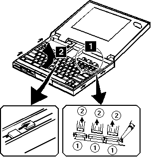
1080 Keyboard Unit #

Source: Hardware Maintenance Manual Volume 2: ThinkPad Computers, p.64

Notes:

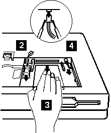
  1. There are two keyboard latches on each side of the computer frame. Slide the keyboard as shown in step 2 to release the keyboard from those latches; them remove the keyboard. (Small arrows on the both sides of the keyboard show the locations of the latches.)
  2. The keyboard has three cables; be careful not to damage the cables when you open the keyboard and to remove them.

Removing the keyboard unit (steps 1 and 2), with insets showing a keyboard latch and the three keyboard cable connectors being released

When Replacing

  • Check that the three keyboard cables are clean, and inserted straight and fully into the connectors. Slide both ends of each connector latch at the same time to make sure that each cable is correctly inserted.
  • Go to Keyboard/Auxiliary Input Device Checkout and test all keys before returning the computer to the customer.

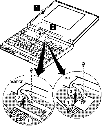
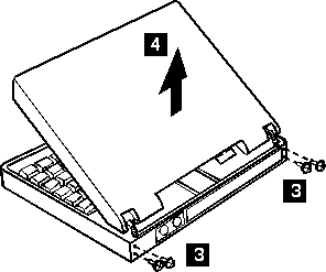
1090 LCD Assembly #

Source: Hardware Maintenance Manual Volume 2: ThinkPad Computers, p.65

Warning Safety Notice 5

If the LCD breaks and the fluid from inside the LCD gets into your eyes or on your hands, immediately wash the affected areas with water for at least 15 minutes. Seek medical care if any symptoms from the fluid are present after washing.

Caring for the LCD

  • When cleaning of the LCD becomes necessary, gently wipe the LCD with a dry, soft cloth. Do not use alcohol or detergent to clean the LCD.
  • To avoid damage to the LCD, do not scratch or apply any force to its surface.
  • Do not put anything on the surface of the LCD.
  • Do not pull the LCD cable. The cable can be damaged if it is disconnected without releasing the latch.

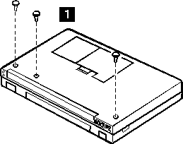
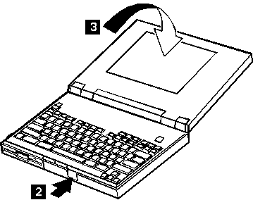
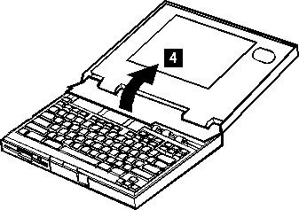
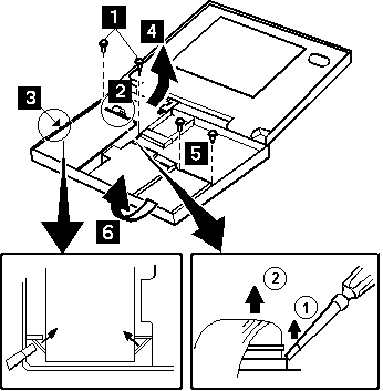
Removing the LCD assembly, steps 1 and 2: remove the screw and disconnect the LCD cable; insets show the 340CSE and 340 connectors

Removing the LCD assembly, steps 3 and 4: remove the hinge screws and lift the LCD assembly off

Use the following table for reference when replacing parts.

Step Location (Quantity) Length
1 LCD cable (1) 6 mm
3 LCD hinge (4) 8 mm

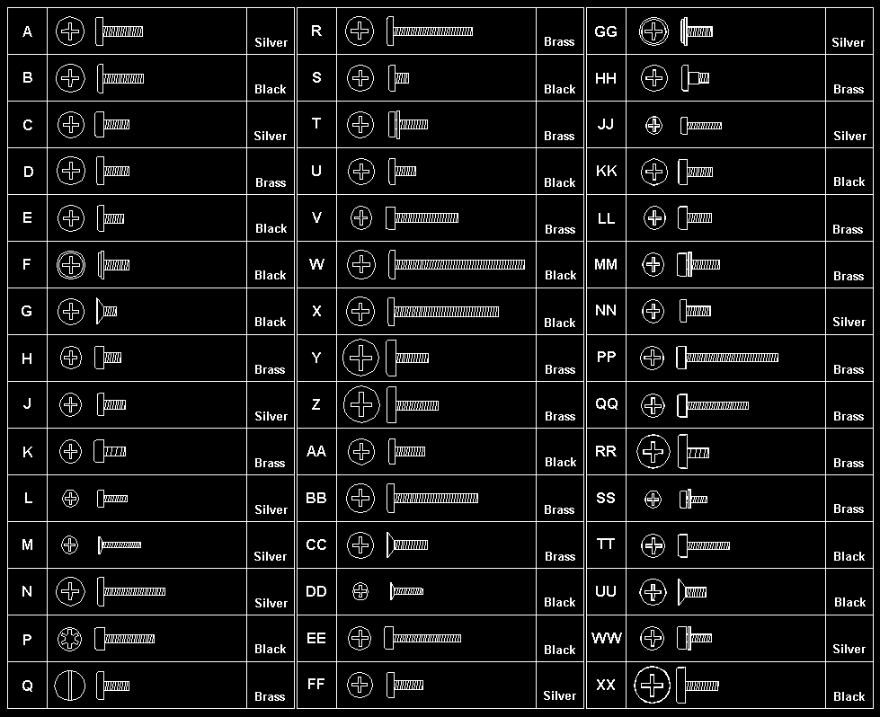
Note: Make sure you use the correct screw. Screw Size Chart

1100 Diskette Drive #

Source: Hardware Maintenance Manual Volume 2: ThinkPad Computers, p.67

1110 Hard Disk Drive

Steps 1, 2, 3, 4: Diskette Drive

Steps 5, 6: Hard Disk Drive

When Replacing

  • Before removing the hard disk drive, have the user make a backup copy of all information on the hard disk
  • Never remove the hard disk drive while the system is operating or is in suspend mode.
  • Do not pull the hard disk cable. The cable can be damaged if it is disconnected without releasing the latch.
  • Do not drop or apply any shock or extra force to the hard disk drive or diskette drive. They are sensitive to physical shock.

Removing the diskette drive (steps 1 to 4) and hard disk drive (steps 5 and 6), with insets showing the latches and a cable connector being released

Use the following table for reference when replacing parts.

Step Location (Quantity) Length
1 Diskette Drive (2) 8 mm
5 Hard Disk Drive (2) 6 mm

Note: Make sure you use the correct screw. Screw Size Chart

1120 System Board/Speaker #

Source: Hardware Maintenance Manual Volume 2: ThinkPad Computers, p.68

The removal drawings for this procedure were not captured; they are on page 68 of the Hardware Maintenance Manual Volume 2.

Step 1, 2, 3, 4: System Board

Step 4, 5: Speaker

Step Location (Quantity) Length
1 I/O connector (6) Hex-head screws
2 Base cover (1) 8 mm
3 Base cover (2) 12 mm

Note: Make sure you use the correct screws.

Locations #

System (Front View)

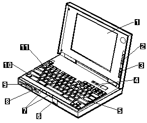
Front view of the ThinkPad 340 with its features numbered 1 to 11

  1. LCD
  2. Contrast Control
  3. Brightness Control
  4. Status Indicator
  5. Keyboard
  6. LCD and Keyboard Latch
  7. Click Button
  8. Diskette-Eject Button
  9. Diskette Drive
  10. Fn Key
  11. TrackPoint II/III

System (Rear View) #

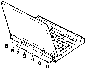
Rear view of the ThinkPad 340 with the connectors numbered 1 to 7

  1. External Display Connector
  2. Serial Connector
  3. PCMCIA Slot
  4. Serial Connector
  5. Reset Pushbutton
  6. Power Jack
  7. External Input Device connector

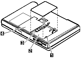
System (Interior View) #

Interior view through the underside, with the backup battery, IC DRAM card slot, standby battery and battery pack numbered 1 to 4

  1. Backup Battery
  2. IC DRAM Card Slot
  3. Standby Battery
  4. Battery Pack

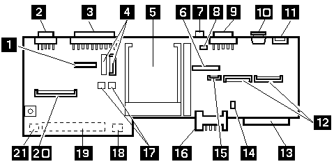
System Board #

Source: Hardware Maintenance Manual Volume 2: ThinkPad Computers, p.37

ThinkPad 340 system board with connectors and switches numbered 1 to 21

  1. Internal Modem Card connector (Modem model only)
  2. External Display Connector
  3. Parallel Connector
  4. LCD connectors
  5. PCMCIA Slot
  6. Indicator Card Connector
  7. Reset Pushbutton
  8. LCD Inverter Power Connector (340CSE)
  9. Serial Connector
  10. Power Jack
  11. External Input Device Connector
  12. Keyboard Signal Connector
  13. Hard Disk Drive Connector
  14. Speaker Connector (340CSE only)
  15. Keyboard TrackPoint II/III Connector
  16. Battery Pack Terminal
  17. POP Terminal
  18. Standby Battery Connector
  19. IC DRAM Card Connector
  20. Diskette Drive Interface
  21. Backup Battery Connector

Flash Memory Update #

System Programs in Flash Memory: System setup programs and diagnostic tests are stored in Flash memory.

Flash Memory Update: A flash memory update is required for the following conditions:

  • Connecting the AC Adapter, and installing the charged battery pack in the computer.
  • New versions of system programs.
  • New features or options are added.

To update the flash memory, do the following.

  1. Get the appropriate diskette which contains the update.
  2. Insert the System Program Service Diskette into drive A and power-on the computer.
  3. Select Update system programs from the menu.

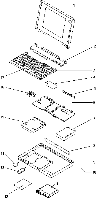
Parts Listing #

Source: Hardware Maintenance Manual Volume 2: ThinkPad Computers, p.72

Exploded view of the ThinkPad 340 with parts numbered 1 to 17

System Unit Models 340 and 340CSE

Index Part FRU P/N
1LCD Assembly (340)84G6678
1LCD Assembly (340CSE)
9.4-inch85G7601
10.4-inch85G7602
2Top Cover (340)84G6677
2Top Cover (340CSE)85G7600
3Keyboard Assembly (See keyboard list)
4Modem/Fax Card (2400 bps.)84G5917
5Indicator Card84G6662
6System Board (340)84G6661
6System Board (25/50MHz)
With modem connector85G7595
Without modem connector85G7596
6System Board (33/66MHz)
Without modem connector
85G7598
7125MB Hard Disk Drive84G6663
200MB Hard Disk Drive85G7606
360MB Hard Disk Drive85G7608
8Rear Connector Cover84G6676
9Base Cover Assembly (340)84G6656
For U.S.84G6890
For Japan84G6659
Base Cover Assembly (340CSE)85G7612
For U.S., Japan85G7611
Note: Base cover assembly includes coil spring, insulator, foot, power switch, knob, holder, latch buttons
10Shield Case84G6660
11Battery Pack (Nickel Cadmium)84G6672
For U.S.84G6671
For Japan84G6674
11Battery Pack (Nickel Metal Hydride)85G7604
12Accessory Cover84G6675
13Standby Battery84G6668
For U.S.84G6667
For Japan84G6670
14Backup Battery84G6666

Screw Kit (Includes the following)

  • 10-2.5 x 4 mm
  • 10-2.5 x 6 mm
  • 10-2.5 x 8 mm, Flat head
  • 10-2.5 x 8 mm
  • 10-2.5 x 16 mm
  • 10-hex stud I/O
  • 10-hex stud bus
  • 2-washers for hex stud bus
84G6764

DASD

Index Part FRU P/N
15Diskette Drive (2-mode)84G6664
Diskette Drive (3-mode)84G6665
16Speaker (360CSE)85G7643
17TrackPoint II Cap66G6444
17TrackPoint III Cap84G6536
Shield Plate (340)84G6774
AC Adapter84G6679
For Japan84G6738
AC Adapter (small, 35W)85G4952
For Japan85G6669
DC Plug85G6664
IC DRAM Card (See options)

Keyboards

Country FRU P/N
Arabic84G6881
Belgium84G6879
Canadian French84G6887
Danish84G6878
Dutch84G6876
Finnish, Swedish84G6875
French84G6872
German (Black)84G6870
Greek84G6885
Hebrew84G6882
Italian84G6874
Japanese84G6888
Latin Spanish84G6886
Norwegian84G6880
Portuguese84G6883
Spanish84G6877
Swiss, French84G6873
Swiss, German84G6871
Turkish84G6884
U.K. English84G6869
U.S. English84G6868

Option Parts List

Notes:

  1. When you replace the AC Adapter with a new one, use the one for the country you are in even if the system is from a different country.
  2. The warranty for the system unit does not apply to all options.
Part FRU P/N
Basic IC DRAM CARD (no parity) 8MB84G5725
Basic IC DRAM CARD (no parity) 4MB84G5724
Basic IC DRAM CARD (no parity) 16MB84G5726
Keyboard/Mouse Cable54G0444
Microphone66G7871
PS/2 Miniature Mouse95F5723
Numeric Keypad
Country FRU P/N
Belgian95F5741
Canadian French95F5466
Danish95F5467
Dutch95F5467
French95F6313
German95F6314
Greek95F5467
Hebrew95F5741
Icelandic95F5467
Italian95F6316
Japanese79F6401
Norwegian95F5467
Spanish95F6315
Swedish/Finnish95F5468
Swiss/French95F5711
Swiss/German95F5715
Turkish95F5467
U.K. English95F5741
U.S. English95F5741
Tools
Part FRU P/N
Tri-Connector Wrap Plug72X8546
PC Test Card35G4703
Audio Wrap Cable66G5180
Screwdriver Kit95F3598
Power Cords

Warning: Use only the power cord certified for your country.

Index Country 30/40W 35W
1Colombia, U.S., Venezuela13F995925H2207
Japan, 2-pin645437785G6665
Japan, 3-pin65F0031—
2Hong Kong, Singapore, U.K.14F003325H2215
3France, Germany, Spain13F997925H2209
4Italy14F006925H2223
5Australia, New Zealand13F994025H2205
6Denmark13F999725H2211
7Israel14F008725H2225
8Bangladesh, Pakistan, Sri Lanka, South Africa14F001525H2213
9Switzerland14F005125H2221
10Thailand183857425H2219

Note: The 30/40W cord is 6 feet long; the 35W cord is 6 inches.

ThinkPad - Common Parts Listing #

This section contains FRUs common to most IBM portable, laptop, and notebook computers.

External Diskette Drives

Part FRU P/N
5.25-Inch Diskette Drives:
360KB External (4869-001) 72X6759
360KB External (4869-501) 72X6768
1.2MB External (4869-002) 15X7993
1.2MB External (4869-502) 15X7994
Hard Disk Drive.
1.2GB HDD (for all 9545) 85G8549
5.25-Inch Drive Adapter 72X6757
5.25-Inch Drive Adapter/A 15F7996
5.25-Inch External Diskette Drive Cable (from system board to adapter) 27F4211
Diskette Drive Bus Adapter 72X8524

CD-ROM Drives

Part FRU P/N
Enhanced Internal CD-ROM II Drive (Eject button below slot) 61G1901
Internal CD-ROM I Drive (Eject button above slot) 81F7930
Terminator Kit (for 81F7930) 59F3530
Cleaning Kit (for 81F7930) (Disks, CD Caddy) 59F3562
Internal CD-ROM II Drive (Eject button below slot) 92F0084
Terminator Kit (for 92F0084) 92F0082
Media Kit (for 92F0084) (No cleaning necessary, Test Disk, CD Caddy) 31F4232
Signal Cable 34F0043
Power Cable 72X8521
Remote ID Switch Cable (3510) 92F0086
Audio Card, Cable, Screws (3510) 92F0085
CD Caddy 22F9419
Rail Kit (3510) 34F0041
Headphones 53F3610

SCSI Adapters, Terminators, Cables

Part FRU P/N
SCSI Adapter/A (without Cache) 85F0002
SCSI Internal Cable 64F4127
SCSI Adapter/A (with Cache) 85F0063
Terminator, External (for 85F0063) 33F8464
Terminator, Internal (for 85F0063) 34F0025
Terminator, Internal (for 85F0002) 57F2870
SCSI Fast Adapter (16 bit) 92F0330
SCSI External Cable (for 92F0330) 32G4089
SCSI Internal Cable (for 92F0330) 32G0084
Terminator, Inline (space permitting) 92F0412

Rewritable Optical Drives

Part FRU P/N
3.5-Inch Rewritable Optical Drive 92F0167
Rewritable Optical Cartridge 38F8647
Rewritable Optical Cartridge (5 Pack) 38F8646
Drive Mounting Slide (for 92F0167) 85F0022
Tray with Bezel (for 92F0167) 85F0021
Objective Lens Cleaner (for 92F0167) 38F8681
Prism Lens Cleaner (for 92F0167) 38F8682
3.5-Inch Enhanced Rewritable Optical Drive 92F0167
Mounting Tray 92F0269
Mounting Tray/Bezel (Model 3510) 92F0268

External Keyboard/Mouse

Part FRU P/N
Keyboard Cable 72X8537
Mouse 61X8923
Mouse Ball and Pop-Off Retainer 33F8461
Mouse Ball and Twist-Off Retainer 33F8462
Mouse (New Style) (33G5420) 06H4595
Mouse Retainer Ring 33G5417
Miniature Mouse 95F5723

Enhanced Keyboards (101/102 Key)

Country FRU P/N
Arabic 1391490
Belgian 1391414
Canadian French 1392011
Cyrillic 1393866
Danish 1391407
Dutch 1391511
French 1391402
German 1391403
Greek 1393285
Hebrew 1391408
Italian 1393395
Latin American Spanish 1392015
Norwegian 1391409
Portuguese 1391410
Russian/Cyrillic 1395622
Spanish 1391405
Swedish/Finnish 1391411
Swiss 1391412
Swiss/French 1395881
Swiss/German 1395882
Turkish 1393286
U.K. English 1391406
U.S. English (E/ME/A use only) 1396790
U.S. English 1392090
Yugoslavian 1393669

Optional Enhanced Keyboards (101/102 Key)

Part FRU P/N
with PS/2 Style Cable 59G7980
with AT Style Cable 59G7981
with 25mm PS/2 Trackball 59G7982
with 25mm Serial Trackball 59G9757

Keybutton Kits (101/102 Key)

Part FRU P/N
Keybutton Kits (R), Belgian 1392033
Keybutton Kits (R), Canadian French 1392032
Keybutton Kits (R), Danish 1392026
Keybutton Kits (R), Dutch 1392034
Keybutton Kits (R), French 6447047
Keybutton Kits (R), German 6447048
Keybutton Kits (R), Italian 6447049
Keybutton Kits (R), Norwegian 1392028
Keybutton Kits (R), Portuguese 1392029
Keybutton Kits (R), Spanish 6447050
Keybutton Kits (R), Spanish / Latin 1392035
Keybutton Kits (R), Swedish 1392030
Keybutton Kits (R), Swiss / French / German 1392031
Keybutton Kits (R), U.K. English 6447046
Keybutton Kits, U.S. English 6447045

Japanese Keyboard Type 2 (106 Key, DBCS Support)

Part FRU P/N
Japanese Keyboard 94X1110
Keyboard Cable 94X1147

Space-Saving Keyboards (84/85 Key)

Part FRU P/N
Canadian French 1396046
Spanish/Latin 1396047
U.S. English 1393290
Cable Assembly, External 1393082

Tools and Miscellaneous

Part FRU P/N
Audio Wrap Cable 66G5180
Ethernet BNC T-Connector 84F8207
Ethernet BNC 50-ohm Terminator (2 required) 85F0037
Grounding Wire Set 38F4684
Keyboard Key Cap Removal Tool 6110464
PC Test Card 33G4703
Screwdriver Kit 95F3598
SCSI Terminator (any SCSI device, space permitting) 92F0142
SCSI Terminator Kit (R-PAC Terminator Modules (3) for 40, 60, 80, 120, and 160MB SCSI Hard Disk Drives) 92F0143
Wrap Plug Ethernet D-Shell 85F0036
Wrap Plug, Tri-Connector 72X8546
Wrap Plug (6157 Tape Attachment Adapter/A) 4178459
Wrap Plug (Token-Ring Network Adapter/A) 6165899
Plastic Envelope (For Wrap Plug) 6138013

TV Tuner #

The TV Tuner Pack (hereafter called TV Tuner) is an option for watching TV programs or videos on the IBM TFT color notebook computer. The computer changes to TV reception when the removable diskette drive is replaced with the TV Tuner.

The TV screen and normal computer display are easily switched by using the Hot key on the front panel of the TV Tuner.

Identifying Names and Functions

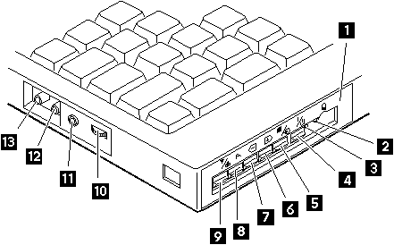
The following figure and table show the names and functions of each part of the TV Tuner.

TV Tuner, showing the front panel controls and the side jacks and connectors numbered 1 to 13

Icons Functions
1 Front Panel Used to change the TV channels, switch TV mode to computer mode, and operate most functions of the TV Tuner.
2 Headphone Jack
Headphone jack
Connects the headphones.
3 Power Indicator Shows the TV Tuner is powered on.
4 Power Switch
Power switch
Powered on and off the TV Tuner.
5 Hot Key
Hot key
Switches between the TV screen and computer screen.
6 Up Switch
Up switch
Increases the value such as the channel number.
7 Down Switch
Down switch
Decreases the value such as the channel number.
8 Function Key
Fn key
Enters the mode to change the value of each function, such as TV channel or color contrast. (See Using the Function Key.)
9 TV/EXT Switch
TV/EXT button
Switches the TV mode or external video mode.
10 Volume Knob
Volume knob
Controls the speaker volume.
11 Audio-In Jack
Audio-in jack
Connects the audio-in connector of the AV cable.
12 Video-In Jack
Video-in jack
Connects video-in connector of the AV cable.
13 RF Connector
RF (antenna) connector
Connects the active antenna unit or antenna cable.

Using the Front Panel

The following table shows how to operate all functions of the TV Tuner with the controls on the front panel.

Key Function
Power
Power switch
Turns on the TV Tuner. This key is used only when the computer is turned on.
Hot Key
Hot key
Switches computer display and TV screen.
Up
Up switch
Increases the value of parameters, Channel Number, Color, Tint, Brightness, Contrast, Auto Tuning Sensitivity, On-screen Message Selection.
Down
Down switch
Decreases the value of parameters, Channel Number, Color, Tint, Brightness, Contrast, Auto Tuning Sensitivity, On-screen Message Selection.
Function
Fn key
Selects a function mode to adjust each function parameter. (See Using the Function Key.)
TV/Ext
TV/EXT button
Switches the displayed video source between the receiving TV broadcast program and external devices such as VCR, video camera recorder, laser disk, and so on.

Safety Notice 8 #

Warning Safety Notice 8

Before removing any FRU, power-off the computer, unplug all power cords from electrical outlets, remove the battery pack, then disconnect any interconnecting cables.

Avant de retirer une unité remplaçable en clientèle, mettez le système hors tension, débranchez tous les cordons d'alimentation des socles de prise de courant, retirez la batterie et déconnectez tous les cordons d'interface.

Die Stromzufuhr muß abgeschaltet, alle Stromkabel aus der Steckdose gezogen, der Akku entfernt und alle Verbindungskabel abgenommen sein, bevor eine FRU entfernt wird.

Prima di rimuovere qualsiasi FRU, spegnere il sistema, scollegare dalle prese elettriche tutti i cavi di alimentazione, rimuovere la batteria e poi scollegare i cavi di interconnessione.

Antes de quitar una FRU, apague el sistema, desenchufe todos los cables de las tomas de corriente eléctrica, quite la batería y, a continuación, desconecte cualquier cable de conexión entre dispositivos.

Safety Notice 3 #

Warning Safety Notice 3

The battery pack contains small amounts of nickel. Do not disassemble it, throw it into fire or water, or short-circuit it. Dispose of the battery pack as required by local ordinances or regulations. Use only the battery in the appropriate parts listing when replacing the battery pack. Use of an incorrect battery can result in ignition or explosion of the battery.

La batterie contient du nickel. Ne la démontez pas, ne l'exposez ni au feu ni à l'eau. Ne la mettez pas en court-circuit. Pour la mettre au rebut, conformez-vous à la réglementation en vigueur. Lorsque vous remplacez la batterie, veillez à n'utiliser que les modèles cités dans la liste de pièces détachées adéquate. En effet, une batterie inappropriée risque de prendre feu ou d'exploser.

Akkus enthalten geringe Mengen von Nickel. Sie dürfen nicht zerlegt, wiederaufgeladen, kurzgeschlossen, oder Feuer oder Wasser ausgesetzt werden. Bei der Entsorgung die örtlichen Bestimmungen für Sondermüll beachten. Beim Ersetzen der Batterie nur Batterien des Typs verwenden, der in der Ersatzteilliste aufgeführt ist. Der Einsatz falscher Batterien kann zu Entzündung oder Explosion führen.

La batteria contiene piccole quantità di nichel. Non smontarla, gettarla nel fuoco o nell'acqua né cortocircuitarla. Smaltirla secondo la normativa in vigore (DPR 915/82, successive disposizioni e disposizioni locali). Quando si sostituisce la batteria, utilizzare soltanto i tipi inseriti nell'appropriato Catalogo parti. L'impiego di una batteria non adatta potrebbe determinare l'incendio o l'esplosione della batteria stessa.

Las baterías contienen pequeñas cantidades de níquel. No las desmonte, ni recargue, ni las eche al fuego o al agua ni las cortocircuite. Deséchelas tal como dispone la normativa local. Utilice sólo baterías que se encuentren en la lista de piezas al sustituir la batería. La utilización de una batería no apropiada puede provocar la ignición o explosión de la misma.

Safety Notice 1 #

Warning Safety Notice 1

Before the computer is powered-on after FRU replacement, make sure all screws, springs, or other small parts are in place and are not left loose inside the computer. Verify this by shaking the computer and listening for rattling sounds. Metallic parts or metal flakes can cause electrical shorts.

Avant de remettre l'ordinateur sous tension après remplacement d'une unité en clientèle, vérifiez que tous les ressorts, vis et autres pièces sont bien en place et bien fixées. Pour ce faire, secouez l'unité et assurez-vous qu'aucun bruit suspect ne se produit. Des pièces métalliques ou des copeaux de métal pourraient causer un court-circuit.

Bevor nach einem FRU-Austausch der Computer wieder angeschlossen wird, muß sichergestellt werden, daß keine Schrauben, Federn oder andere Kleinteile fehlen oder im Gehäuse vergessen wurden. Der Computer muß geschüttelt und auf Klappergeräusche geprüft werden. Metallteile oder -splitter können Kurzschlüsse erzeugen.

Prima di accendere l'elaboratore dopo che é stata effettuata la sostituzione di una FRU, accertarsi che tutte le viti, le molle e tutte le altri parti di piccole dimensioni siano nella corretta posizione e non siano sparse all'interno dell'elaboratore. Verificare ciò scuotendo l'elaboratore e prestando attenzione ad eventuali rumori; eventuali parti o pezzetti metallici possono provocare cortocircuiti pericolosi.

Antes de encender el sistema despues de sustituir una FRU, compruebe que todos los tornillos, muelles y demás piezas pequeñas se encuentran en su sitio y no se encuentran sueltas dentro del sistema. Compruébelo agitando el sistema y escuchando los posibles ruidos que provocarían. Las piezas metálicas pueden causar cortocircuitos eléctricos.