ThinkPad Laptops

ThinkPad 300

Machine Type 2615 · 1992 · 19 sections

One of the first ThinkPads, built for IBM by Zenith Data Systems in 1992: a 25 MHz 386SL notebook with a 3.5-inch diskette drive, an 80MB or 120MB hard disk and a monochrome or colour screen.

This transcribed historical service reference may contain incomplete captures. The linked original manuals remain authoritative.

Service Reference

Product Overview #

Two variants side by side, compiled from a hardware survey and IBM's product records. A value spanning several columns applies to each of those variants; a dash means no source records it.

Specifications by variant
Specification ThinkPad 300 ThinkPad 300C
Released October 1992
Processor Intel 386SL, 25 MHz (soldered QFP package)
Bus AT bus
Memory Standard 4 MB; maximum 12 MB; proprietary memory
Storage 2.5" IDE: 80 or 120 MB; drive connects through an internal cable
Display 9.5" passive matrix greyscale, 640 × 480 8.4" active matrix, 640 × 480
Graphics Cirrus Logic GD6410
Audio PC speaker
Main battery NiMH
CMOS battery NiCad
Power connector Zenith proprietary connector
Media drives 3.5" 1.44 MB floppy drive
PC Card slots None
Networking Modem, AAUI Ethernet
Ports
  • Parallel
  • Serial
  • VGA out
  • PS/2
  • Docking connector
Pointing device None
IBM model codes — 1 model of machine type 2615
VariantModel codes
ThinkPad 3002615-ALL

Status Indicators #

Source: Hardware Maintenance Manual Volume 1: Laptop, Notebook, Portable and ThinkPad Computers, p.205

Light State Status Indicated
Battery status indicator Green Battery pack is full.
Amber Battery pack is being fast charged.
Amber (flashing) Battery pack temperature is out of operational range.
Red Problem in battery circuit.
Off
  • Computer is operating from battery pack.
  • Battery pack is removed from computer.
  • Computer is off.
  • Computer is using external power (car battery or AC power).
AC power indicator On Computer is attached to AC power
Standby mode indicator On Standby mode is active
Battery power indicator On Computer is operating from battery
Hard disk drive in-use indicator On Hard disk drive is active
Diskette drive in-use indicator On Diskette drive is active
Port replicator indicator On Port replicator is attached
External video indicator On External video is enabled
Modem indicator On Modem is enabled
LAN controller indicator On LAN controller is enabled
Speaker indicator On Speaker is enabled
Num Lock indicator On Keyboard is in Num Lock mode
Caps Lock indicator On Keyboard is in Caps Lock mode
Scroll Lock indicator On Keyboard is in Scroll Lock mode
Numeric keypad lock indicator On Imbedded keypad is locked on

General Checkout #

Source: Hardware Maintenance Manual Volume 1: Laptop, Notebook, Portable and ThinkPad Computers, p.196

Start here. The ThinkPad 300 was built for IBM by Zenith Data Systems, and its service procedures differ from other ThinkPads': the diagnostics are started from the Monitor program, and the numeric error codes have six digits.

Attention Important

The diagnostic tests are intended to test only IBM products. Non-IBM products, prototype card, or modified options can give false errors and invalid computer responses.

  1. Power-off the computer and all external devices.
  2. Insert the Advanced Diagnostics diskette into the diskette drive.
  3. Power-on all external devices, then power-on the computer.
  4. Press Ctrl+Alt+Ins to start the Monitor program.
  5. At the Monitor-program prompt, type BF then press Enter.
  6. Follow the instructions on the screen and run the diagnostics tests. For information on how to disable a password, see Power-On Password.

    Note: Press F1 to access the help screens.

  7. If you receive an error or message, find your symptom below, then go to the appropriate page.
Symptom Go to ...
Numeric Error Code Symptom-to-FRU Index
Error Messages Miscellaneous Symptoms

Note: For information about how to run diagnostics, passwords, and various other tests, go to Related Service Procedures.

How to Run the Diagnostics #

  1. Power-off the computer and all external devices.
  2. Insert the Advanced Diagnostics diskette into diskette drive.
  3. Power-on all external devices, then power-on the computer.
  4. Press Ctrl+Alt+Ins to start the Monitor program.
  5. At the Monitor-program prompt, type BF then press Enter.
  6. Follow the instructions on the screen and run the diagnostics tests.

    Note: Press F1 to access the help screens.

PREP - Hard Disk Low Level Format #

Source: Hardware Maintenance Manual Volume 1: Laptop, Notebook, Portable and ThinkPad Computers, p.206

The PREP utility initializes and prepares the hard disk surface for the storage of data. It performs a low-level format, then checks for bad sectors. If any bad sectors are found, they are marked in a way that prevents data from being stored in them.

There are two situations where PREP is used.

  • To prepare the hard disk drive surface for formatting when installing a new hard disk drive.
  • To exclude sectors of the hard disk that have become unusable, indicated by intermittent or continuous hard disk drive read failures.

Attention Warning

PREP erases all data on the hard disk. If at all possible, always back up the data on the hard disk to diskettes before running PREP.

Symptom-to-FRU Index #

Source: Hardware Maintenance Manual Volume 1: Laptop, Notebook, Portable and ThinkPad Computers, p.197

On this page IBM's index continues in separate sections: Numeric Error Codes, Miscellaneous Symptoms and Failed Device to FRU Index.

The Symptom-to-FRU Index lists symptoms, errors, and the possible causes. The most likely cause is listed first. Use this index to help you decide which FRUs to have available when servicing the computer.

Note: For IBM devices not supported by the ThinkPad 300 diagnostic code, refer to the manual for that device.

Miscellaneous Symptoms #

Source: Hardware Maintenance Manual Volume 1: Laptop, Notebook, Portable and ThinkPad Computers, p.202

Symptom/Error FRU/Action
AC Adapter connected, no charge light
  1. Replace AC Adapter
  2. Battery pack
  3. Video/power board
Red Charge LED
  1. Replace battery
  2. Video/power board
No display and no status icons
  1. System board
  2. Video/power board
Display blank, any status icon on
  1. Top cabinet/LCD
  2. Video/power board
Rest/Resume problem
  1. Check setup
  2. Backup battery
  3. System board
  4. Video/power board
Won't boot from diskette
  1. Check setup
  2. Diskette drive
  3. Video/power board
Won't boot from hard disk
  1. Check Setup
  2. Hard disk
  3. Video/power board
Time/Date problems
  1. Backup battery
  2. System board
LCD not readable
  1. Top cabinet/LCD
  2. Video/power board
No backlight
  1. Top cabinet/LCD
  2. Video/power board
No system
  1. Install the operating system. Refer to operating system documentation.
  2. Re-enter the boot command syntax and make certain a valid drive was selected.
Non-maskable interrupt received!
  1. If a software problem is suspected, have the customer contact the software manufacturer or dealer and report the problem.
  2. Use the Advanced Diagnostics to test the computer.
  3. Replace AC adapter.
Retries exhausted, Please remove diskette
  1. Power-off computer, then try reprogramming with another Advanced Diagnostics diskette.
  2. Replace system board.
Error programming FLASH Device. Retrying The Flash ROM is not accepting data.
  1. Replace system board.
Device failure! Device content has been corrupted
  1. Replace system board.
Remove floppy and re-insert to try again, else reboot
  1. Follow the instructions listed. If this does not work, power-off computer, wait 15 seconds, then power-on. Try reprogramming with another Advanced Diagnostics diskette.
  2. Replace system board.
Device error during erasing process
  1. Replace system board.
Device error during programming process
  1. Replace DC-to-DC board.
  2. Replace system board.
Program verify failure
  1. Replace system board.

Failed Device to FRU Index #

Source: Hardware Maintenance Manual Volume 1: Laptop, Notebook, Portable and ThinkPad Computers, p.204

Whenever a diagnostic test fails, an error message is displayed indicating what device failed. The following table cross references a failed device message to the failing FRU.

Diagnostic Message FRU
CPU
  1. Main Board
Real Time Clock
  1. Main Board
Math Coprocessor
  1. Math Coprocessor
  2. Main Board
DMA Controller
  1. Main Board
Speaker
  1. Bottom Cabinet Assy
Flash ROM
  1. Main Board
Interrupt Controller
  1. Main Board
Interval Timer Circuit
  1. Main Board
System Control Processor
  1. Main Board
COM1 Serial Port
  1. Main Board
COM2 Serial Port
  1. Main Board
Parallel Port (378H)
  1. Main Board
Parallel Port (278H)
  1. Main Board
CPU Crystal
  1. Main Board
Interval Timer Crystal
  1. Main Board
Interrupt Control Circuit
  1. Main Board
PS/2 Mouse Circuit
  1. Main Board
Video Controller
  1. Video Board
Video Memory
  1. Video Board
Hard Drive Controller (0)
  1. Hard Drive
  2. Video Board
Hard Drive (0)
  1. Hard Drive
  2. Video Board
Floppy Drive Controller
  1. Video Board
Floppy Drive
  1. Diskette Drive
Parity
  1. Main Board
Cache Circuity
  1. Main Board
Cache Data RAM
  1. Main Board
Cache Tag RAM
  1. Main Board
Base Memory
  1. Main Board
Extended Memory
  1. Memory Module
  2. Main Board
Configuration RAM
  1. Main Board
Modem
  1. Modem
  2. Video Board

Numeric Error Codes #

Source: Hardware Maintenance Manual Volume 1: Laptop, Notebook, Portable and ThinkPad Computers, p.197

Symptom/Error FRU/Action
200006 - Hard Drive Error
  1. Check drive cable connection.
  2. Boot the computer from the diskette drive, back up the hard drive, then prep and format the hard drive.
  3. Replace hard drive.
  4. Replace video/power board.
200007 - Hard Drive Error
  1. Check drive cable connection.
  2. Boot the computer from the diskette drive, back up the hard drive, then prep and format the hard drive.
  3. Replace hard drive.
  4. Replace video/power board.
200008 - Hard Drive Error
  1. Check drive cable connection.
  2. Replace hard drive.
  3. Replace video/power board.
200009 - Hard Drive Error
  1. Check drive cable connection.
  2. Reinstall the operating system on the hard disk.
  3. Boot the computer from the diskette drive, back up the hard drive, then prep and format the hard drive.
200102 - Diskette Error
  1. Make sure diskette is properly formatted and inserted.
  2. Try a different diskette.
  3. Check all cable connections.
  4. Replace diskette drive.
  5. Replace video/power board.
200103 - Diskette Error
  1. Make sure diskette is properly formatted and inserted.
  2. Try a different diskette.
  3. Check all cable connections.
  4. Replace diskette drive.
  5. Replace video/power board.
200104 - Diskette Error
  1. Remove any non-system diskettes when powering on the computer.
  2. Make sure diskette has a bootable operating system on it.
200105 - Diskette Error
  1. Reformat the diskette.
  2. Replace the diskette.
  3. Replace video/power board.
200110 - Floppy Drive Error
  1. Make sure diskette is fully inserted into the drive.
  2. Make sure diskette is formatted.
  3. Try a different diskette.
  4. Replace diskette drive.
  5. Replace video/power board.
200112 - Floppy Drive Error
  1. Check drive cable connection.
  2. Replace diskette drive.
  3. Replace video/power board.
  4. Replace system board.
200113 - Floppy Drive Error
  1. Check drive cable connection.
  2. Replace diskette drive.
  3. Replace video/power board.
  4. Replace system board.
200301 - Memory Error
  1. Power-off computer, wait 15 seconds, then power-on.
  2. If the message reappears, replace system board.
200302 - Memory Error
  1. Power-off computer, wait 15 seconds, then power-on.
  2. If the message reappears, replace system board.
200303 - Memory Error
  1. Power-off computer, wait 15 seconds, then power-on.
  2. Perform BIOS update. See BIOS Update Procedure.
  3. Replace system board.
200304 - Memory Error
  1. Replace system board.
200305 - Memory Error
  1. Perform BIOS update. See BIOS Update Procedure.
  2. Replace system board.
200307 - Memory Error
  1. Charge battery, re-enter configuration data in Setup, power-off computer, then power-on.
  2. Replace backup battery.
  3. Replace system board.
200308 - Memory Error
  1. Make sure memory modules are properly seated in their sockets.
  2. Use Setup to confirm that the hardware configuration is correct.
  3. Run Advanced Diagnostics to determine what hardware is failing.
  4. Replace memory modules if errors are above 2MB.
  5. Replace system board if errors are below 2MB or if replacing memory modules did not help.
200351 - PMI Error. An SVGA monitor is required to run the application that is to be resumed.
  1. This message appears if an SVGA monitor was attached when the system entered suspend mode, but it was not found when the system resumed.
  2. Attach an SVGA monitor before resuming.
200352 or 200353 - PMI Error
  1. Retry the operation after the computer is finished accessing the diskette drive.
200354 - PMI Error
  1. Insert the diskette that was in the computer when it was rested.
200355 - PMI Error
  1. Retry the operation after modem or serial port activity is finished.
  2. Replace system board.
200402, 200403, 200404, 200405 - Memory Error
  1. Power-off computer, wait 15 seconds, then power-on.
  2. Replace system board.
200453 or 200459 - Configuration Error. This message is normal after backup battery replacement.
  1. Use the Setup program to reconfigure.
  2. Replace backup battery.
  3. Replace system board.
200456 - Configuration Error
  1. Use the Setup program to verify extended RAM memory size matches memory installed.
  2. Ensure memory module is proper installed.
  3. Use Advanced Diagnostics to test extended memory. If you cannot boot computer, replace system board and retry.
    • If the tests identify an expansion memory module (memory above 2MB), replace it.
    • If the tests identify a problem in the memory below 2MB, replace system board.
200458 - Configuration Error
  1. Use Setup program to reconfigure.
  2. Make sure the drive is bootable.
  3. Replace hard drive.
  4. Replace system board.
200552 - Error
  1. Verify keyboard is properly connected.
  2. Replace keyboard.
  3. Replace system board.
200553 - Error
  1. Recharge the battery pack.
  2. Replace battery pack.
  3. Replace video/power board.
200554 - Error
  1. Replace battery pack.
  2. Replace video/power board.
200555 - Error
  1. Reboot computer and enter the correct password.
200556 or 200557 - Error
  1. Try another copy of the software, or have the customer contact the software manufacturer or dealer and report the problem.
  2. Power-off computer, wait 15 seconds, then power-on. If the message reappears, replace system board.
200558 - Error
  1. Try another copy of the software, or have the customer contact the software manufacturer or dealer and report the problem.
  2. Power-off computer, make sure all external cable connections are secure, wait 15 seconds, and then power-on. If the message reappears, replace system board.

FRU Removals and Replacements #

Source: Hardware Maintenance Manual Volume 1: Laptop, Notebook, Portable and ThinkPad Computers, p.209

The exploded view that this sequence follows is not reproduced on this page; it is on PDF page 211 of the Hardware Maintenance Manual, Volume 1.

Removals and replacements

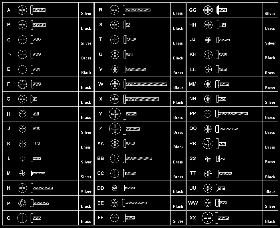
Follow the numerical sequence in the FRU removal sequence list and in the exploded view to remove or disconnect parts in the correct order. The letters in parentheses in the list indicate screw types. See the Screw Size Chart to match the letters to the correct screw type and size before replacing each screw.

Warning Safety Notice 8: Translation

Before removing any FRU, power-off the computer, unplug all power cords from electrical outlets, remove the battery pack, then disconnect any interconnecting cables.

Safety Notice 1: Translation

Before the computer is powered-on after FRU replacement, make sure all screws, springs, or other small parts are in place and are not left loose inside the computer. Verify this by shaking the computer and listening for rattling sounds. Metallic parts or metal flakes can cause electrical shorts.

  1. Battery Pack
  2. Coprocessor Cover
  3. Three Top Cover Screws (1-B, 2-TT) (At rear of keyboard)
  4. Five Bottom Cover Screws (4-B, 1-UU) (One is inside battery compartment)
  5. LCD Cable
  6. LCD Ribbon Cable
  7. LCD Assembly
  8. One Keyboard Screw (D) (At front of keyboard)
  9. Two Ribbon Cables
  10. Keyboard Assembly
  11. Four System Board Screws (D)
  12. Two Threaded Hex Spacers (At rear of system board)
  13. System Board
  14. Three Hard Disk Drive Screws (D)
  15. Hard Disk Drive and Mounting Brackets (Have customer backup all information before replacing drive. Do not replace the hard drive if the computer is operating or is in suspend mode. Restore drive system information using the customer's backup copy of the system programs.)
  16. Diskette Drive Ribbon Cable
  17. Diskette Drive
  18. Backup Battery
  19. Speaker
  20. Five Threaded Spacers
  21. Video/Power Board

Locations #

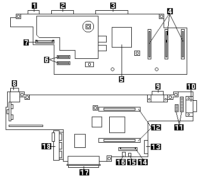
System Board

System board locations for the ThinkPad 300, with connectors numbered 1 to 18

  1. Serial Connector
  2. Parallel Connector
  3. Port Replicator Connector
  4. Memory Module Connectors
  5. Math Coprocessor Connector
  6. Keyboard Connector
  7. Status Light Panel Connector
  8. AC Adapter Connector
  9. External Display Connector
  10. LAN Connector
  11. LCD Connectors
  12. System Board Connectors
  13. Modem Connector
  14. Diskette Connector
  15. Speaker Connector
  16. Backup Battery Connector
  17. Hard Disk Drive Connector
  18. Battery Contacts

Power-On Password #

Source: Hardware Maintenance Manual Volume 1: Laptop, Notebook, Portable and ThinkPad Computers, p.206

Passwords

To override a password, do the following.

  1. Power-off the computer.
  2. Remove the access panel.
  3. Remove the battery pack.
  4. Remove the top assembly (do not disconnect any cables).
  5. Connect a jumper to the two pads (R39) at the side of the math coprocessor socket.
  6. Reinstall the battery pack.
  7. Power-on the computer. Keep the computer on until the LEDs blink and the system locks.
  8. Remove the jumper.
  9. Press and hold the reset switch, then power-on the computer.
  10. Power-off the computer.
  11. Replace the top assembly and the access panel.

Read or Set - LAN ID / Set EEPROM #

Read LAN ID

Select this field to read the current LAN ID number that is programmed into the main board.

Set LAN ID

Select this field to program a new LAN ID number into the main board.

Set EEPROM

Select this field to program the EEPROM. It allows you to set LCD display type (monochrome or color) and enable or disable the LAN option, if installed.

BIOS Update Procedure #

Source: Hardware Maintenance Manual Volume 1: Laptop, Notebook, Portable and ThinkPad Computers, p.207

Use this procedure to reprogram the computer's BIOS. The computer contains the latest version of BIOS available when manufactured, but later revisions might be available. There are two reasons for replacing the BIOS.

  1. To have a more recent version of BIOS that adds features that enhance the computer's performance.
  2. To reinstall the BIOS on a computer in which the BIOS has become corrupt.

After you select this option, the current BIOS version will be displayed. You will be asked if you want to overwrite the current BIOS version. If you answer Yes, the computer will look for the BIOS image file on drive A and install it.

Note: Always operate the computer on AC power when updating the BIOS.

Parts Listing #

Source: Hardware Maintenance Manual Volume 1: Laptop, Notebook, Portable and ThinkPad Computers, p.213

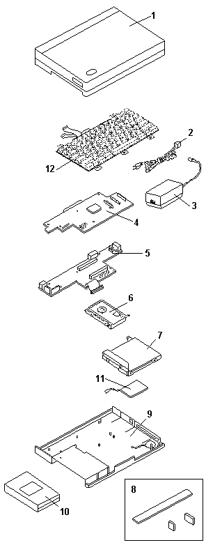
Exploded view of the ThinkPad 300 with parts numbered 1 to 12

System Unit (300)

Index Description FRU No.
1Top Cover Assembly, Monochrome33G9301
1Top Cover Assembly, Color33G9320
2Power Cord, US6952301
2Power Cord, UK14F0033
2Power Cord, Switzerland14F0051
2Power Cord, Europe13F9979
3A.C. Power Cube33G6490
4System Board, Monochrome (US)33G9297
4System Board, Color (US)33G9487
4System Board, Monochrome (Europe)33G9488
4System Board, Color (Europe)33G9489
–2MB Memory Module33G9310
–8MB Memory Module33G9311
5Video/Power Board33G9296
8Parts Pack, Cover33G9302
9Bottom Cover Assembly33G9305
10Battery Pack33G9298
11Backup Battery33G9295
–Speaker33G9475
–Parts Package, Screws33G9303
–Parts Package, Covers33G9302
12See Keyboards (300)–

DASD (300)

Index Description FRU No.
680MB Hard Disk Drive33G9306
6120MB Hard Disk Drive33G9307
7Diskette Drive33G9304

Options and Adapters (300)

Description FRU No.
AC Adapter, Power Cube33G6490
Charging Cradle33G9312
NiMH Battery33G9298
Port Replicator (standard)33G9313
Ethernet Adapter (thin)33G9308
Ethernet Adapter (twisted pair)33G9309
Modem, 2400 BPS, US92F8846
Fax/Modem, US92F8896
Fax/Modem, Worldwide33G6293
Fax/Modem DAA Adapter, US92F8847
Fax/Modem DAA Adapter, UK92F8848
Fax/Modem DAA Adapter, Danish92F8849
Fax/Modem DAA Adapter, French92F8850
Fax/Modem DAA Adapter, German92F8851
Fax/Modem DAA Adapter, Italian92F8852
Fax/Modem DAA Adapter, Norwegian92F8853
Fax/Modem DAA Adapter, Spanish92F8854
Fax/Modem DAA Adapter, Swedish92F8855
Fax/Modem DAA Adapter, Swiss92F8856
Fax/Modem DAA Adapter, Australia33G9284
Fax/Modem DAA Adapter, New Zealand33G9387
Fax/Modem DAA Adapter, Latin America92F9288
BIOS Update Diskette33G9490

Keyboards (300)

Description FRU No.
Belgian33G9423
Canadian33G9422
Danish33G9424
Dutch33G9425
French33G9324
German33G9317
Italian33G9318
Latin America Spanish33G9431
Norwegian33G9426
Portuguese33G9427
Spanish33G9319
Swedish/Finnish33G9428
Swiss33G9430
U.K. English33G9316
U.S. English33G9315
Numeric Keypad33G9314

Tools

Description FRU No.
Tri-Connector Wrap Plug72X8546
PC Test Card35G4703
Audio Wrap Cable66G5180
Screwdriver Kit95F3598

Safety Notice 8 #

Warning Safety Notice 8

Before removing any FRU, power-off the computer, unplug all power cords from electrical outlets, remove the battery pack, then disconnect any interconnecting cables.

Avant de retirer une unité remplaçable en clientèle, mettez le système hors tension, débranchez tous les cordons d'alimentation des socles de prise de courant, retirez la batterie et déconnectez tous les cordons d'interface.

Die Stromzufuhr muß abgeschaltet, alle Stromkabel aus der Steckdose gezogen, der Akku entfernt und alle Verbindungskabel abgenommen sein, bevor eine FRU entfernt wird.

Prima di rimuovere qualsiasi FRU, spegnere il sistema, scollegare dalle prese elettriche tutti i cavi di alimentazione, rimuovere la batteria e poi scollegare i cavi di interconnessione.

Antes de quitar una FRU, apague el sistema, desenchufe todos los cables de las tomas de corriente eléctrica, quite la batería y, a continuación, desconecte cualquier cable de conexión entre dispositivos.

Safety Notice 1 #

Warning Safety Notice 1

Before the computer is powered-on after FRU replacement, make sure all screws, springs, or other small parts are in place and are not left loose inside the computer. Verify this by shaking the computer and listening for rattling sounds. Metallic parts or metal flakes can cause electrical shorts.

Avant de remettre l'ordinateur sous tension après remplacement d'une unité en clientèle, vérifiez que tous les ressorts, vis et autres pièces sont bien en place et bien fixées. Pour ce faire, secouez l'unité et assurez-vous qu'aucun bruit suspect ne se produit. Des pièces métalliques ou des copeaux de métal pourraient causer un court-circuit.

Bevor nach einem FRU-Austausch der Computer wieder angeschlossen wird, muß sichergestellt werden, daß keine Schrauben, Federn oder andere Kleinteile fehlen oder im Gehäuse vergessen wurden. Der Computer muß geschüttelt und auf Klappergeräusche geprüft werden. Metallteile oder -splitter können Kurzschlüsse erzeugen.

Prima di accendere l'elaboratore dopo che é stata effettuata la sostituzione di una FRU, accertarsi che tutte le viti, le molle e tutte le altri parti di piccole dimensioni siano nella corretta posizione e non siano sparse all'interno dell'elaboratore. Verificare ciò scuotendo l'elaboratore e prestando attenzione ad eventuali rumori; eventuali parti o pezzetti metallici possono provocare cortocircuiti pericolosi.

Antes de encender el sistema despues de sustituir una FRU, compruebe que todos los tornillos, muelles y demás piezas pequeñas se encuentran en su sitio y no se encuentran sueltas dentro del sistema. Compruébelo agitando el sistema y escuchando los posibles ruidos que provocarían. Las piezas metálicas pueden causar cortocircuitos eléctricos.