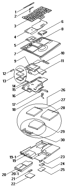
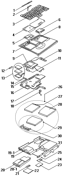
Product Overview #
The ThinkPad 390 and 390E are flexible desktop-replacement laptops featuring integrated floppy and CD-ROM drives.
Product Overview
The following shows an overview of the system features of the computer.
| Feature | Description |
|---|---|
| Processor | TP 390/i Series 1700 ° Intel® Pentium® MMX ™ processor 233 MHz, L2 cache ° Intel® Pentium® II processor 233 MHz, L2 cache ° Intel® Pentium® II processor 266 MHz, L2 cache TP 390E ° Intel® Mobile Pentium® II processor 300 MHz, L2 cache ° Intel® Mobile Pentium® II processor 333 MHz, L2 cache ° Intel® Mobile Celeron ™ processor 300 MHz, L2 cache |
| Bus architecture | PCI Bus |
| Memory | 2 DIMM slots, no memory on the planar board 32 MB, 64 MB or 128 MB DIMM card (max. 256 MB) |
| CMOS RAM | 114 bytes + 4 Kbytes |
| Video | ° 12.1-inch, 64K colors, 800x600 pixel TFT color LCD ° 13.3-inch, 64K colors, 1024x768 pixel TFT color LCD ° 14.1-inch, 64K colors, 1024x768 pixel TFT color LCD |
| Audio | ° 16-bit audio ° Internal stereo speakers ° Internal microphone ° Wavetable MIDI |
| Diskette drive | 1.44MB (3-mode), 3.5-inch |
| Hard disk drive | TP 390/i Series 1700 ° 3.2 GB, 2.5-inch, IDE interface ° 4.0 GB, 2.5-inch, IDE interface TP 390E ° 3.2 GB, 2.5-inch, IDE interface ° 4.0 GB, 2.5-inch, IDE interface ° 6.4 GB, 2.5-inch, IDE interface ° 10.0 GB, 2.5-inch, IDE interface |
| CD-ROM drive | TP 390/i Series 1700 5.25-inch, 20X speed, E-IDE interface TP 390E 5.25-inch, 24X speed, E-IDE interface |
| I/O ports | ° External monitor ° Headphone/line-out ° Line-in ° Microphone-in ° Mouse/keyboard ° Parallel ° Serial ° USB ° RJ11 |
| Infrared transfer | IrDA 1.1 |
| Internal modem | 56Kbps (depends on the model) PCI |
| PC Card (PCMCIA) | One Type III or two Type II CardBus, ZV port support |
| AC Adapter | 56-Watt type |
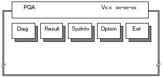
 Attention Before running the PQA Diagnostic Program,
make sure that the write enable tab of the Diagnostic Program Diskette is set to enable.
Attention Before running the PQA Diagnostic Program,
make sure that the write enable tab of the Diagnostic Program Diskette is set to enable.
 Numeric Error Codes
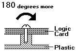
 Safety Notice 1:
 Setting the LCD Panel ID
 How to Disable the Password