ThinkPad Laptops

ThinkPad 770

Machine Types 9548 / 9549 · 1997–99 · 64 sections

IBM's high-end multimedia notebook of 1997–99, sold as the 770, 770E/770ED, 770X and 770Z with Pentium MMX or Pentium II processors, a 13.3- to 14.1-inch TFT screen and an UltraBay II drive bay. The notes below follow IBM's ThinkPad 770 Series Hardware Maintenance Manual, in which the CPU card and DC-DC card are FRUs separate from the system board.

This is a transcribed historical service reference and may contain incomplete captures. Consult the linked original manuals as the authoritative sources before servicing.

Service Reference

Product Overview #

Five variants side by side, compiled from a hardware survey and IBM's product records. A value spanning several columns applies to each of those variants; a dash means no source records it.

Specifications by variant
Specification ThinkPad 770 ThinkPad 770E ThinkPad 770ED ThinkPad 770X ThinkPad 770Z
Released October 1997 April 1998 October 1998 February 1999
Processor Intel Pentium MMX (Tillamook), 200 or 233 MHz Intel Mobile Pentium II, 266 MHz Intel Mobile Pentium II, 300 MHz Intel Mobile Pentium II, 366 MHz
Chipset Intel 430TX Intel 440BX
Memory Standard 32 MB; maximum 256 MB; EDO or SDRAM, 2 × 144-pin slots Standard 32 MB; maximum 288 MB; SDRAM, 2 slots Standard 64 MB; maximum 288 MB; SDRAM, 2 slots Standard 64 or 128 MB; maximum 288 MB; SDRAM, 2 slots Standard 128 MB; maximum 320 MB; SDRAM, 2 slots
Storage 2.5" IDE: 3.2, 4.0 or 5.1 GB; drive adapter required 2.5" IDE: 5.1 GB; drive adapter required 2.5" IDE: 8.1 GB; drive adapter required 2.5" IDE: 14.1 GB; drive adapter required
Display
  • 13.3" active matrix, 1024 × 768
  • 14.1" active matrix, 1024 × 768
14.1" active matrix, 1024 × 768
  • 13.7" active matrix, 1280 × 1024
  • 14.1" active matrix, 1024 × 768
  • 14.1" TFT, 1024 × 768
  • 13.7" TFT, 1280 × 1024
Graphics Trident Cyber9397, 2 MB video memory Trident Cyber9397E, 4 MB video memory Trident Cyber9397DVD, 4 MB (XGA) or 8 MB (SXGA) video memory Trident Cyber9397DVD, 4 MB (XGA models) or 8 MB (SXGA models) video memory
Audio Crystal CS4237B with stereo speakers and microphone Crystal CS4239 with stereo speakers and microphone Crystal CS4239
Main battery Lithium-ion
CMOS battery
  • CR2430 lithium CMOS battery (socketed)
  • 3-cell Varta NiMH reserve battery
Power connector Barrel jack
Media drives
  • UltraBay II
  • DVD-ROM drive (optional; standard on 14.1" models)
  • UltraBay II
  • DVD-ROM drive (optional)
  • UltraBay II
  • DVD-ROM drive (standard)
  • UltraBay II
  • DVD-ROM drive (optional)
PC Card slots
  • 2 × CardBus
  • Zoomed Video support
Networking Modem (optional) Modem
Ports
  • Parallel
  • Serial
  • VGA out
  • PS/2
  • USB 1.x
  • Docking connector
  • External floppy connector
  • Line in
  • Line out
  • Infrared
BIOS IBM BIOS with Easy-Setup
Pointing device TrackPoint
IBM model codes — 111 models of machine types 9548 and 9549
VariantModel codes
ThinkPad 7709548-300, 9548-30F, 9548-30J, 9548-30K, 9548-30P, 9548-30S, 9548-30U, 9548-310, 9548-31F, 9548-31J, 9548-31U, 9548-32U, 9548-400, 9548-40F, 9548-40J, 9548-40P, 9548-40S, 9548-40U, 9549-1A0, 9549-1AA, 9549-1AF, 9549-1AJ, 9549-1AK, 9549-1AP, 9549-1AS, 9549-1AU
ThinkPad 770E9548-510, 9548-51A, 9548-51E, 9548-51F, 9548-51J, 9548-51P, 9548-51S, 9548-51U, 9548-520, 9548-52A, 9548-52F, 9548-52J, 9548-52P, 9548-52S, 9548-52U, 9548-530, 9548-53U
ThinkPad 770ED9549-5A0, 9549-5AA, 9549-5AC, 9549-5AF, 9549-5AH, 9549-5AJ, 9549-5AP, 9549-5AS, 9549-5AT, 9549-5AU
ThinkPad 770X9549-710, 9549-71A, 9549-71C, 9549-71F, 9549-71J, 9549-71K, 9549-71P, 9549-71S, 9549-71T, 9549-71U, 9549-72A, 9549-72F, 9549-72U, 9549-73U, 9549-7AA, 9549-7AF, 9549-7AG, 9549-7AJ, 9549-7AK, 9549-7AP, 9549-7AS, 9549-7AU, 9549-7B0, 9549-7BA, 9549-7BF, 9549-7BJ, 9549-7BU
ThinkPad 770Z9549-810, 9549-81A, 9549-81C, 9549-81E, 9549-81F, 9549-81H, 9549-81K, 9549-81P, 9549-81S, 9549-81T, 9549-81U, 9549-820, 9549-82A, 9549-82E, 9549-82F, 9549-82U, 9549-83U, 9549-8A0, 9549-8AA, 9549-8AC, 9549-8AF, 9549-8AH, 9549-8AK, 9549-8AP, 9549-8AS, 9549-8AT, 9549-8AU, 9549-8B0, 9549-8BA, 9549-8BF, 9549-8BU

Using the Function Key #

This is the Function key on the front panel of the optional TV Tuner, not the keyboard Fn key; see TV Tuner for the other controls. In the table, <- and +> stand for the Down and Up switches.

Each time you press the Function key (Fn key), one of the following messages (called On-Screen Message) appears at the top left corner of the LCD.

The changed values are automatically saved when you return to the “TV Channel” On-Screen message. The values are not saved when you power-off the TV Tuner without returning to this message.

Message on LCD Parameter
(xx)

TV Channel

By using <- and +>, you can select the channels from 2 to 69.

COL

Color Adjustment

By pressing and holding <- or +>, you can change the color.

TNT

TINT Adjustment

By pressing and holding <- or +>, you can change the tint.

BRT

Bright Adjustment

By pressing and holding <- or +>, you can change the brightness.

CNT

Contrast Adjustment

By pressing and holding <- or +>, you can change the contrast.

---

(No function)

Reserved.

LO
HI

Auto Tune Sensitivity Selection

LO: Means the sensitivity of the TV is low. In this mode, the TV Tuner receives strong TV signals only. To set LO, press <-.

HI: Means the sensitivity of the TV is high (factory default). In this mode, the TV Tuner receives weak and strong TV signals. To set HI, press +>.

D3S
DON

Time On-Screen Message appears

D3S: On-Screen Message appears for 3 seconds. To set D3S, press <-.

DON: On-Screen Message always appears. To set DON press +>.

Checkout Guide #

Source: ThinkPad 770 Series (9548, 9549) Hardware Maintenance Manual, p.36

Start here. IBM's entry procedure for the ThinkPad 770 series: verify the symptom, then use the table to find the procedure to follow.

Use the following procedure as a guide for computer problems.

Note: The diagnostic tests are intended to test only IBM products. Non-IBM products, prototype cards, or modified options can give false errors and invalid system responses.

  1. Obtain the failing symptoms in as much detail as possible.
  2. Verify the symptoms by attempting to re-create the failure by running the diagnostic test or by repeating the same operation.

    Note: To run the diagnostics, refer to Running the Diagnostics.

  3. Use the following table with the verified symptom to determine which page to go to. Search the “Symptoms (Verified)” column, and find the description that best matches your symptom; then go to the page shown in the “Go To” column.

    Symptoms (Verified) Go To
    Power failure. (The power indicator does not go on or stay on.) Power Systems Checkout.
    POST does not complete. No beep or error codes are indicated. Symptom-to-FRU Index section, and then use the No Beep Symptoms table.
    POST beeps, but no error codes are displayed. Symptom-to-FRU Index section, and then use the Beep Symptoms table.
    POST detected an error and displayed numeric error codes. Symptom-to-FRU Index section, and then use the Numeric Error Codes table.
    The diagnostic test detected an error and displayed a FRU code. FRU Codes.
    The configuration is not the same as the installed devices. Checking the Installed Devices List.
    Other symptoms (such as LCD display problems). Symptom-to-FRU Index section, and then use the Other Symptoms table.
    Symptoms cannot be re-created (intermittent problems). Use the customer-reported symptoms and go to Symptom-to-FRU Index section.

Audio Checkout #

Source: ThinkPad 770 Series (9548, 9549) Hardware Maintenance Manual, p.37

ISA Audio Check Out

  1. Go to the diagnostic menu by selecting Test in the Easy-Setup menu.
  2. Select Audio and run the diagnostic tests.
  3. If the test detects a audio problem, replace the system board.

PCI Audio Check Out

  1. Power off the computer.
  2. Insert the ThinkPad Hardware Maintenance Diskette Version 1.05 or later version into the diskette drive.
  3. Power on the computer.
  4. Select Test the audio feature from the main menu.
  5. If FAIL is displayed on the screen, replace the system board.

Diskette Drive Checkout #

Source: ThinkPad 770 Series (9548, 9549) Hardware Maintenance Manual, p.37

Do the following to isolate the problem to a controller, drive, or diskette. A blank, formatted, write-enabled, nondefective 2HD diskette is required.

FDD-1 represents the diskette drive in the bay. FDD-2 represents an external diskette drive.

Attention: Make sure that the diskette does not have more than one label attached to it. Multiple labels can cause damage to the drive or cause the drive to fail.

Do the following to select the test device. See Running the Diagnostics for details.

  1. Start Easy-Setup.
  2. Click on Test.
  3. Press Ctrl+A to enter the advanced diagnostic mode. The ThinkPad FRU Connections window appears.
  4. Click on Exit. The keyboard layout window appears.
  5. Click on Exit.
  6. Click on FDD-1 or FDD-2 to start the test.
  7. Insert the blank diskette when instructed and follow the instructions on the screen.
  8. If the controller test detects an error, FRU code 10 appears. Replace the system board.
  9. If the controller test runs without errors, the drive read/write tests start automatically. If a drive test detects an error, FRU code 50 for FDD-1 or 51 for FDD-2 appears. If the diskette itself is known to be good, replace the drive.

Fan Checkout #

Source: ThinkPad 770 Series (9548, 9549) Hardware Maintenance Manual, p.38

To check the fan, do the following:

  1. Start Easy-Setup.
  2. Click on Test. The fan will start so you can check the air turbulence at the louver near the power switch.
  3. Press Ctrl+A to enter the advanced diagnostic mode. The ThinkPad FRU Connections window appears. If the fan connector is not connected, Fan not connected message appears.
  4. Click on Exit. The keyboard layout window appears.
  5. Click on Exit.
  6. Click on System Board and press Enter to run the test. Follow the description on the window. If the test detects the fan problem, replace it.

Indicator LED Checkout #

Source: ThinkPad 770 Series (9548, 9549) Hardware Maintenance Manual, p.38

If an indicator LED problem occurs, do the following:

  1. Power off the computer.
  2. Power on the computer. All the LEDs should turn on for a moment after the computer is powered on.
  3. Verify that all LEDs turned on. If some of the LEDs do not turn on, replace the card that the LEDs are on. If the problem persists, replace the system board.

Indicator Panel Checkout #

Source: ThinkPad 770 Series (9548, 9549) Hardware Maintenance Manual, p.38

If an indicator panel problem occurs, do the following:

  1. Power off the computer.
  2. Power on the computer. All the icons should turn on for a moment after the computer is powered on.
  3. Verify that all icons appear correctly. If some of the icons do not appear, replace the card that the indicator panel is connected to. If the problem persists, replace the DC-DC card.

Keyboard or Auxiliary Input Device Checkout #

Source: ThinkPad 770 Series (9548, 9549) Hardware Maintenance Manual, p.38

Remove the external keyboard if the internal keyboard is to be tested.

If the internal keyboard does not work or an unexpected character appears, make sure that the flexible cable extending from the keyboard is correctly seated in the connector. If the keyboard cable connection is correct, run the keyboard test. See Running the Diagnostics for details.

Note: When the Fn key is pressed, a black square briefly appears.

If the tests detect a keyboard problem, do the following one at a time to correct the problem. Do not replace a nondefective FRU:

  1. Reseat the keyboard cable.
  2. Replace the keyboard.
  3. Replace the card that the keyboard is connected to.
  4. Replace the system board.

The following auxiliary input devices are supported for this computer:

  • Numeric keypad
  • Mouse (PS/2 compatible)
  • External keyboard (with keyboard/mouse cable)

If any of these devices do not work, reseat the cable connector and repeat the failing operation.

If the problem does not recur, recheck the connector. If the problem is not corrected, replace the device and then the card that the devices are directly connected to.

Memory Checkout #

Source: ThinkPad 770 Series (9548, 9549) Hardware Maintenance Manual, p.39

DIMM cards are available for increasing memory capacity.

The memory size is displayed in kilobytes. 576 KB is reserved by the system, so you calculate the memory size by the following equation:

[total memory size (MB)] × 1024 − 576 (KB)

For example, if the total memory size is 64 MB, it is displayed as 64960 KB.

Memory errors might stop system operations, show error messages on the screen, or hang the system.

Use the following procedure to isolate memory problems:

  1. Power off the computer and remove any installed DIMM from its slot.

    Note: If the computer has a base memory slot and option memory slots, remove any DIMMs installed in the option memory slots.

  2. Press and hold the F1 key; then power on the computer. Hold the F1 key down until the Easy-Setup menu appears.
  3. Select Test and press Enter.
  4. Select Memory and press Enter to run the memory test on base memory.

    See Running the Diagnostics for details.

    If an error appears:

    • If the computer don't have the base memory slot, replace the system board.
    • If the computer has the base memory slot, remove the DIMM installed in the base memory slot and go to step 2. Then if an error appears, replace the system board.

    If an error does not appear, continue the following procedures.

  5. Power off the computer and reinstall the DIMM one by one; then power on the computer. Verify the memory size; then test the memory. If an error appears, replace the DIMM.

    Note: Make sure that the DIMM is fully installed into the connector. A loose connection can cause an error.

  6. If the problem does not corrected, replace the following FRU.
    1. System board
    2. CPU card

If memory problems occur intermittently, use the loop option to repeat the test. When the test detects an error, an error log is printed on the printer connected to the parallel port. See Displaying the Error Log for more information.

System Programs in Flash Memory

System setup programs and diagnostic tests are stored in the Flash memory.

Flash Memory Update

The Flash memory update is required for the following conditions:

  • New versions of system programs
  • New features or options

To update the Flash memory, do the following:

  1. Get the appropriate diskette containing the update.
  2. Insert the System Program Service Diskette into drive A and power on the computer.
  3. Select Update system programs from the menu.

Port Replicator Checkout #

Source: ThinkPad 770 Series (9548, 9549) Hardware Maintenance Manual, p.41

Use the following procedure to isolate a port replicator problem. The port replicator attaches to the system expansion connector at the rear of the computer:

  1. Power off the computer.
  2. Remove the failing devices from the port replicator.
  3. Unplug the AC Adapter from the port replicator, if attached.
  4. Remove the port replicator from the computer.
  5. Reconnect the failing device directly to the computer. (If another device is already connected to the computer, remove it first.)
  6. Go to the Running the Diagnostics and run the diagnostics.
  7. If the advanced diagnostic device test did not find an error, suspect a problem with the port replicator.
  8. Power off the computer and reconnect the port replicator.
  9. Power on the computer and run the following advanced diagnostic tests:
    • Serial port test with the wrap plug installed on the port replicator
    • Universal serial bus test with the USB parallel test cable
    • Parallel port test with the wrap plug installed on the port replicator
    • FDD-2 device test on the failing device with a scratch diskette
  10. If diagnostic errors appear, replace the port replicator or the diskette drive. If the problem remains after the replacement, replace the system board.
  11. If power problems appear only when the port replicator is used, replace the port replicator.

System Board and CPU Card Checkout #

Source: ThinkPad 770 Series (9548, 9549) Hardware Maintenance Manual, p.45

The processing functions are performed by both the system board and the CPU card. Processor problems can be caused by either FRU. However, the CPU card generally has a lower probability of failure. If a numeric code indicates the system board or the CPU card as a failing FRU, or the CPU card is indicated by a diagnostic test by showing FRU code 11, use the following procedure to isolate the problem:

  1. Run the system board test to verify the symptom. This test verifies both the system board and the CPU card. If no error is detected, return to Checkout Guide.

    Note: Don't touch the keyboard and pointing device when the system board test is running. This might cause an unexpected error.

  2. If FRU code 10 appears, replace the system board but do not replace the CPU card. Remove the CPU card from the old system board and install it to the new system board.
  3. If FRU code 11 appears, reseat the CPU card.
  4. Rerun the test to verify the fix.
  5. If FRU code 11 remains, replace the CPU card.

If this procedure does not correct the problem, go to the Undetermined Problems section for each model.

TrackPoint Checkout #

Source: ThinkPad 770 Series (9548, 9549) Hardware Maintenance Manual, p.45

If the TrackPoint does not work, check the configuration in the ThinkPad Configuration program. If the configuration of the TrackPoint is disabled, select Enable to enable it.

If this does not correct the TrackPoint problem, continue with the following. After you use the TrackPoint, the pointer drifts on the screen for a short time. This self-acting pointer movement can occur when a slight, steady pressure is applied to the TrackPoint pointer. This symptom is not a hardware problem. No service actions are necessary if the pointer movement stops in a short period of time.

If a click button problem or the pointing stick problem occurs, do the following:

  1. Go to the Easy-Setup menu.
  2. Select an item with the pointing stick.
  3. Press any one of the click buttons.
  4. Verify that the item is selected.
  5. Move to another item with the pointing stick.
  6. Press the pointing stick (press-to-select), and verify that the item is selected.

    Note: This step is only for the model that has the press-to-select function.

  7. Verify that all buttons work correctly.

If either the pointing stick or the click button do not work, do the following actions one at a time to correct the problem. Do not replace a nondefective FRU.

  1. Reseat the keyboard cables.
  2. Replace the keyboard.
  3. Reseat the card that the TrackPoint cable is directly connected to.
  4. Replace the system board.

Checking the Installed Devices List #

Source: ThinkPad 770 Series (9548, 9549) Hardware Maintenance Manual, p.49

If a device is installed but the icon appears in a gray shade rather than a dark shade on the basic diagnostics menu, the device is defective. If necessary, adjust the contrast control to clearly distinguish the shades of the icon. Reseat the device connectors. If the symptom remains, replace the device or the system board.

If a device that is not installed appears in a dark shade (for example, FDD-2 appears in a dark shade when no second FDD is installed), do the following:

  1. Replace the first device in the configuration, such as an FDD-1.
  2. If the problem persists, replace the card that the device is connected to.

The Parallel, and Serial icons are always displayed in a dark shade, because the icons represent subsystems of the system board and not the attachment of devices.

The FDD-1 icon represents a device in the computer. The FDD-2 icon represents another device, such as:

  • An external diskette drive attached to the computer
  • An external diskette drive attached to a port replicator
  • A diskette drive in a docking station

Common Devices Checkout #

Source: Hardware Maintenance Manual Volume 4: ThinkPad Computers, p.693

IBM's Volume 4 manual gathers the checks for devices shared by many ThinkPad models into a separate Common Devices Checkout chapter. Its sections are on this page:

External Diskette Drive Test #

Source: Hardware Maintenance Manual Volume 4: ThinkPad Computers, p.694

Use the following procedure to isolate the diskette problem to a controller, drive or diskette. A scratch, write-enabled 2HD diskette is required.

  1. Select the icon FDD on the TEST MENU. By doing this, the controller test and the drive read/write test run. If the controller test detects an error, FRU code 10 appears. In this case, replace the system board.
  2. If the controller test run without errors, follow the instructions on the screen and insert a scratch diskette.
  3. If the drive test detects an error, FRU code 50 appears. If the diskette media are known to be good, replace the drive or the drive cable.

External Keyboard / Auxiliary Input Device Checkout #

Source: Hardware Maintenance Manual Volume 4: ThinkPad Computers, p.695

The following auxiliary input devices may be available for IBM ThinkPad models.

  • Numeric keypad
  • Mouse (PS/2 compatible)
  • External keyboard (with Keyboard/Miniature Mouse cable)
  • If you suspect a problem with any of the auxiliary input devices (listed above), replace the device.

    If the problem is not corrected, replace the following FRUs one at a time to correct the problem.

    • Keyboard control card
    • System board
  • If the computer receives an incorrect keyboard response, remove other external devices, check the keyboard connections, and recheck the keyboard responses. If the problem remains, replace the following FRUs one at a time to correct the problem.

    • Keyboard
    • Keyboard control card
    • System board
  • If a 00030100 error message appears, power-off the computer and the external devices. Then power-on the computer before you power-on the external devices.

Fax/Modem Checkout #

Source: Hardware Maintenance Manual Volume 4: ThinkPad Computers, p.696

001
  • Power-off the computer.
  • Ensure that the modem is installed correctly.
  • If the modem never worked in customer mode, ensure that all drivers are loaded correctly onto the computer.
  • Ensure that the communication program is supported on the computer.
  • Ensure that the public switch telephone network (PSTN) cable and the data access arrangement (DAA) cable, if installed, are connected correctly.

If you need to correct one of the above conditions, do so now; then continue.

Note: PCMCIA cards can be inserted and removed while the system is powered on.

  • Power-on the system.
  • Insert the IBM Data/FAX Modem diskette into the default diskette drive.
  • If you are servicing a High Speed Internal Data/Fax Modem (Models FC3632 and FC3650), at the DOS prompt (for example, A:\), type IBMDIAG; then press Enter.
  • If you are servicing a PCMCIA Data/FAX Modem (Models FC3634 and FC3635), at the DOS prompt (for example, A:\), type ESTDIAG; then press Enter.
  • Follow the instructions on the screen. (If you need help, press F1.)

Did the diagnostic tests detect an error?

Yes — go to Step 003. No — go to Step 002.

002

The diagnostic tests have completed successfully. If you suspect a problem, go to Step 004.

003

Go to the Symptom-to-FRU Index for the computer you are servicing.

004
  • Check the PSTN cable and the DAA cable, if installed, for continuity.

Is the cable(s) good?

Yes — go to Step 006. No — go to Step 005.

005

Replace the defective cable(s).

006
  • Have the customer transmit a call.

Was the call transmitted successfully?

Yes — go to Step 008. No — go to Step 007.

007

Go to Step 011.

008
  • Have the customer receive an incoming call on the modem.

Was the incoming call received?

Yes — go to Step 010. No — go to Step 009.

009

Go to Step 014.

010

The diagnostic tests have completed successfully. If you still suspect a problem that is not software related, replace the External DAA; then replace the modem.

011
  • Have the customer transmit a call at a lower speed.

Was the call transmitted successfully?

Yes — go to Step 013. No — go to Step 012.

012

If installed, replace the external DAA. If you do not have an external DAA installed, or replacing the external DAA does not correct the problem, replace the modem.

013

Have the telephone line checked.

014
  • Have the customer receive an incoming call on the modem at a lower speed.

Was the incoming call received?

Yes — go to Step 016. No — go to Step 015.

015

If installed, replace the external DAA. If you do not have an external DAA installed, or replacing the external DAA does not correct the problem, replace the modem.

016

Have the telephone line checked.

Printer Checkout #

Source: Hardware Maintenance Manual Volume 4: ThinkPad Computers, p.698

  1. Make sure the printer is correctly connected and is powered-on.
  2. Run the printer self-test.

If the printer self-test does not run correctly, the problem is in the printer. Refer to the printer service manual.

If the printer self-test runs correctly, do the following.

  1. Verify the port settings in configuration.
  2. Install a wrap plug on the port (indicated in configuration) and run the advanced diagnostic tests.
  3. If the advanced diagnostic tests (with the wrap plug installed) do not detect a failure, replace the printer cable. If the problem is not corrected, replace the system board.

TrackPoint II Checkout #

This is the general TrackPoint II procedure from IBM's Common Devices Checkout chapter. The ThinkPad 770's own procedure is TrackPoint Checkout.

  • If the TrackPoint II does not work, check the configuration. If the configuration of the TrackPoint II is set to Disabled or Off, change it to Enable or On. If the problem remains, continue.

    Note: TrackPoint II automatically compensates to adjust the pointer sensor. This causes the pointer to move slightly on the screen and then stop. Pointer movement might occur when a slight, steady pressure is applied to the TrackPoint II pointer when the computer is powered-on or running, or when exceeded temperature range requires re-adjustment.

  • If the cursor floats or moves erratically, power-off and disconnect the mouse. Power-on the computer. If the problem goes away, replace the mouse. If the problem remains, replace the keyboard.
  • For click button or pointing stick problems:

    1. Go to the Easy-Setup screen.
    2. Select an item with the pointing stick.
    3. Press either left or right click button.
    4. Verify that both buttons work correctly.

    If the pointing stick or the click button does not work, do the following.

    1. Reseat the keyboard cables.
    2. Replace the keyboard.
    3. Replace the interposer card (355x, 360x, 750x, 755x).
    4. Replace keyboard control card (720).
    5. Replace the system board.

Power Systems Checkout #

Source: ThinkPad 770 Series (9548, 9549) Hardware Maintenance Manual, p.42

To verify the symptom of the problem, power on the computer using each of the following power sources:

  1. Remove the battery pack.
  2. Connect the AC Adapter and check that power is supplied.
  3. Disconnect the AC Adapter and install the charged battery pack; then check that power is supplied by the battery pack.

If you suspect a power problem, see the appropriate power supply checkout in the following list:

Power-on the TV Tuner #

Use the ThinkPad Features program or PS2.EXE. to power-on the TV Tuner; then power-on the internal device in the diskette drive compartment.

Attention Warning

If power for the internal device is turned off when the TV Tuner is set up, nothing appears on the LCD display. Turn on power for the TV Tuner again.

  • If you are using DOS, do one of the following:

    • Power-on the computer and type PS2 from the command prompt to start the ThinkPad Features program.

      Select Set Power Features from the ThinkPad Features menu; then put a check mark at Internal Serial Port (or Diskette Drive Compartment) under the Power for devices. If you need help, press F1 to display the help menu.

    • Type PS2 MODEM ON (or PS2 DDC ON) from the command prompt; press the Enter key to set the power ON.
  • If you are using OS/2 or Microsoft Windows, do the following:

    1. Power-on the computer and start the ThinkPad Features program.
    2. Select the Power icon; then move the pointer to Internal Serial Port (or Diskette Drive Compartment) under the Power for devices and click the button to check mark it.
    3. Press the OK button.

Checking the AC Adapter #

IBM's drawing of the AC Adapter plug is not reproduced on this page; see page 42 of the ThinkPad 770 Series HMM (PDF).

You are here because the computer fails only when the AC Adapter is used:

  1. If the power problem occurs only when the port replicator is used, replace the port replicator.
  2. If the power-on indicator does not turn on, check the power cord of the AC Adapter for correct continuity and installation.
  3. If the operational charge does not work, go to Checking Operational Charging.
  4. Unplug the AC Adapter cable from the computer and measure the output voltage at the plug of the AC Adapter cable. See the following figure:

    (16 - 10 V)

    Pin Voltage (V dc)
    1+15.5 to +17.0
    2Ground
  5. If the voltage is not correct, replace the AC Adapter.
  6. If the voltage is within the range, do the following:
    • Replace the system board.
    • If the problem is not corrected, go to Undetermined Problems section of each model.

Note: An audible noise from the AC Adapter does not always indicate a defect.

Checking Operational Charging #

To check operational charging, use a discharged battery pack or a battery pack that has less than 50% of the total power remaining when installed in the computer.

Perform operational charging. If the battery status indicator or icon does not turn on, remove the battery pack and let it return to room temperature. Reinstall the battery pack. If the charge indicator or icon still does not turn on, replace the battery pack.

If the charge indicator still does not turn on, replace either the system board or DC-DC card that the battery is connected to. Then reinstall the battery pack. If the reinstalled battery pack is not charged, go to the next section.

Checking the Battery Pack #

IBM's drawing of the battery terminals is not reproduced on this page; see page 43 of the ThinkPad 770 Series HMM (PDF).

Battery charging will not start until the Fuel-Gauge shows that less than 95% of the total power remains; with this condition the battery pack can charge to 100% of its capacity. This protects the battery pack from being overcharged or having a shortened life.

Do the following:

  1. Power off the computer.
  2. Remove the battery pack and measure the voltage between battery terminals 1 (+) and 4 (−). See the following figure:

    Terminal Voltage (V dc)
    1+0 to +12.6
    4Ground (−)
  3. If the voltage is less than +11.0 V dc, the battery pack has been discharged. Recharge the battery pack.

    Note: In this case, the battery pack is over-discharged. It takes at least 3 hours to recharge the battery pack even if the indicator does not turn on.

  4. If the voltage is still less than +11.0 V dc after recharging, replace the battery.
  5. If the voltage is more than +11.0 V dc, measure the resistance between battery terminals 3 and 4. The resistance must be 4 to 30 K ohm.
  6. If the resistance is not correct, replace the battery pack. If the resistance is correct, replace the system board.

Checking the Car-Battery Adapter #

IBM documents this check only in the ThinkPad 760 and 765 chapters of its Volume 4 manual (vol4hmm, PDF page 228); neither ThinkPad 770 manual includes it, and the voltages below come from the 760 chapter. It is kept here for reference only.

  1. Unplug the Car-Battery Adapter cable from the computer.
  2. Plug the Car-Battery Adapter into the cigarette lighter socket.

    Note: If the adapter is already plugged in, reseat it.

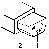
  3. Measure the output voltage of the Car-Battery Adapter cable. See the following figure:

    Rectangular DC plug of the adapter cable with pins 1 and 2 labelled for measuring the output voltage

    Pin Voltage (V dc)
    1+19.0 to +21.0
    2Ground
    • If the voltage is correct, the Car-Battery Adapter is working correctly. Check that the computer runs with the AC Adapter. If it runs correctly with the AC Adapter, check the system board. If the problem still remains, replace the following FRUs one at a time.

      1. DC/DC card
      2. System board

      If the problem is not resolved when the system board is replaced, go to Undetermined Problems.

    • If the voltage is outside the normal voltage range, do one of the following:

      • Try these test procedures in a different car, if one is available.
      • Replace the Car-Battery Adapter if the computer works correctly with the AC Adapter.

Note: If the output voltage from the cigarette lighter socket of the car is less than 10.5 V dc, a continuous noise may be heard. The condition of the car battery should be checked by appropriate service personal.

Checking the Backup Battery #

IBM's drawing of the backup battery is not reproduced on this page; see page 44 of the ThinkPad 770 Series HMM (PDF).

Do the following:

  1. Power off the computer and unplug the AC Adapter from the computer.
  2. Turn the computer upside down.
  3. Remove the backup battery (see Removal and Replacement section of each model).
  4. Measure the voltage of the backup battery. See the following figure.

    Note: Be careful not to measure the wrong side of the backup battery.

    Wire Voltage (V dc)
    Red+2.5 to +3.2
    BlackGround
  • If the voltage is correct, replace the system board.
  • If the voltage is not correct, replace the backup battery.
  • If the backup battery discharges quickly after replacement, replace the system board.

Checking the Standby Battery #

The ThinkPad 770 Series HMM has no standby-battery check; this procedure is from the ThinkPad 770 chapter of IBM's Volume 4 manual, where its drawing of the battery connector is on PDF page 549.

  1. Power off the computer and unplug the AC Adapter from the computer.
  2. Remove the battery pack and keyboard.
  3. Remove the standby battery. (Refer to 1100 Standby Battery to remove the battery.)

    Attention: Be careful not to cause a short circuit when measuring the voltage.

  4. Measure the voltage of the standby battery.
    • If the voltage between red and black wire of the battery is 3.5 V dc or greater, the voltage is correct. Go to step 10 to verify standby battery operation.
    • If the voltage is less than 3.5 V dc, go to the next step.
  5. Plug the AC Adapter into the computer and power on the computer.

    Attention: Be careful not to cause a short circuit when measuring the voltage.

  6. With the battery unplugged, measure the output voltage at the connector.

    Pin Voltage (V dc)
    ++4.0
    −Ground
    • If the voltage is less than +4.0 V dc, replace the DC/DC card. If the voltage is still low, replace the system board.
    • If the voltage is more than +4.0 V dc, power off the computer, replace the standby battery, and go to the next step.
  7. Ensure that the AC Adapter is plugged into the computer; then power on the computer.
  8. Charging of the standby battery starts immediately. A depleted battery needs approximately 30 minutes to be recharged to the operational voltage of +3.5 V dc.
  9. Unplug the AC Adapter.
  10. Verify the standby battery function by removing and installing the battery pack during suspend mode.

    Note: Removing and installing the battery pack during suspend mode should be done within 1 minute. If the system does not resume after a charged battery pack is installed, replace the DC/DC card.

    If replacing the DC/DC card does not resolve the problem, replace the system board.

Port Replicator Power Overload #

If power shutdown occurs intermittently when PC Card devices are used through a port replicator with PC Card slots, suspect an over-current problem. Some PC Card devices use more power; if the maximum usage of each device occurs simultaneously, the total current will exceed the limit, thereby causing a power shutdown. Isolate this problem by removing one of the devices, use the computer under the same condition, and see whether a power shutdown occurs. Do this procedure for all devices to determine the cause.

Running the Diagnostics #

Source: ThinkPad 770 Series (9548, 9549) Hardware Maintenance Manual, p.46

IBM's drawing of the USB test-cable connections is not reproduced on this page; see page 48 of the ThinkPad 770 Series HMM (PDF).

The following table lists the special tools needed for the diagnostics:

Tool Name Part Number
PC test card35G4703
Tri-connector wrap plug72X8546
USB parallel test cable05K2580

Use either the TrackPoint or the cursor-moving keys to interact with the tests. The Enter key works the same as selecting the OK icon to reply OK.

  1. Press and hold F1; then power on the computer. Hold F1 down until the Easy-Setup menu appears.
  2. Click on Test. The basic diagnostic menu appears.
  3. Click on a device to run the test. The test progress screen appears; then OK appears under the tested device icon when the test ends without any errors.
  4. Start the Advanced Diagnostic test by pressing Ctrl+A on the basic diagnostic menu. The ThinkPad FRU connections window appears.
  5. Click on Exit or press the Esc key. The keyboard test window appears.
  6. When you press a key, a mark appears or disappears on the corresponding key position on the screen. Repeat this step for any keys that need to be tested. You can run the keyboard test if you press Ctrl+K in the advanced diagnostic test mode.
  7. To exit the keyboard test, click on Exit or press Ctrl+Break. The advanced diagnostics window appears.
  8. Click on a device to test it, or click on Test All to test all devices.

    Click on Looptest to run the tests in a repeated loop. The loop option menu appears. Click on a device; the √ mark appears beside the selected device. Repeat this step to select multiple devices. Click on OK to start the diagnostic loop. If no device is selected, all devices tests are looped.

  9. To exit the loop, keep pressing Ctrl+Pause until the test exits. A beep sounds to notify that the exit interrupt is sensed by the test program. Press Esc to exit from the loop test.

PC Card Slots Test

The green LED on the PC test card turns on when the PC Card slot test is running. If the LED does not turn on, check that the card is installed correctly by reseating it. If the LED still does not turn on after the card is reseated, try using another slot for the test. If the LED still does not turn on and the test fails, replace the FRU shown by the diagnostic error code.

Universal Serial Bus (USB) Test

At the advanced diagnostic window, do the following:

  1. Connect the USB parallel test cable to the parallel connector of the computer.
  2. Connect Connector 1 of the cable to the USB connector of the computer.

    Note: The illustration shows a ThinkPad 770 computer, but the procedure is the same for the other model.

  3. Click on USB-1 to run the test.

    Follow the instructions on the screen. OK appears if the test passed, but three lines of error codes appear if the test failed. The defective FRU must be the system board.

    If you want to test the USB port on the port replicator, connect the USB parallel test cable to a port replicator and click on USB-2.

    If you want to test the USB ports on a docking station, connect the USB parallel test cable to the USB ports of the docking station and click on USB-3 and USB-4.

Displaying the Error Log

Diagnostic errors are printed on a printer attached to the parallel port when the error is detected. The error is also logged in the system memory.

Use the following procedure to display the errors:

  1. Enter the advanced diagnostic test.
  2. Press Ctrl+E.
  3. The error log appears.
  4. To exit the screen, click on Exit or press Esc.

The error log is not saved when system power is turned off.

External Display Self-Test #

Source: Hardware Maintenance Manual Volume 4: ThinkPad Computers, p.694

If the display problem occurs only when using an external display, use the following instructions to correct the problem.

Note: Before you replace a display, check the following list to see if it is connected correctly.

  • 8506 and 8508 displays must be connected to an Image Adapter/A or an Image-I Adapter/A.
  • 63XX and 85XX systems support either 63XX or 85XX displays.
  • 85XX systems with an XGA-2 adapter support 95XX displays.
  • 95XX systems support either 63XX, 85XX, or 95XX displays.
  • ThinkPad models support either 85XX or 95XX displays.

If the screen is rolling, replace the display assembly. If that does not correct the problem, replace FRUs in the following order until the problem goes away:

  1. Video card
  2. Display adapter (any type)
  3. System board
  4. Bus adapter (if used)

If the screen is not rolling, run the display self-test as follows:

  1. Power-off the computer and display.
  2. Disconnect the display signal cable.
  3. Power-on the display.
  4. Set the contrast to its maximum position.
  5. Set the brightness control to the center detent position.

Check for the following conditions:

  • You should be able to vary the screen intensity by adjusting the contrast and brightness controls.
  • The screen should be white or light gray, with a black margin (test margin) on the screen.

    Note: The location of the test margin varies with the type of display. The test margin might be on the top, bottom, or one or both sides.

If you do not see a test margin on the screen, replace the display. If there is a test margin on the screen, replace the system board.

Note: On ThinkPad Models 700, 700C, 720C, 720C, do the following:

  1. Video card
  2. System board

Symptom-to-FRU Index #

Source: ThinkPad 770 Series (9548, 9549) Hardware Maintenance Manual, p.58

The symptom-to-FRU index lists the symptoms and errors and their possible causes. The most likely cause is listed first.

Note: Perform the FRU replacement or actions in the sequence shown in the “FRU/Action in Sequence” column. If a FRU replacement did not solve the problem, put the original part back in the computer. Do not replace a nondefective FRU.

This index can also help you determine the next possible FRUs to be replaced when servicing a computer.

Numeric error codes show the errors detected in POST or system operation. In the following error codes, X can be any number.

If no codes are available, use narrative symptoms.

If the symptom is not listed, go to Undetermined Problems.

Note: For IBM devices not supported by diagnostic codes in the ThinkPad notebook computers, see the manual for that device.

Beep Symptoms #

Source: ThinkPad 770 Series (9548, 9549) Hardware Maintenance Manual, p.63

Symptom / Error FRU / Action in Sequence
Continuous beeps.
  1. Reseat the CPU card.
  2. Reseat the video card.
  3. System board
One beep and a blank, unreadable, or flashing LCD.
  1. Reseat the LCD connector.
  2. Reseat the CPU card.
  3. LCD assembly
  4. System board
  5. CPU card
One beep, and the message Unable to access boot source.
  1. Boot device
  2. System board
One long and two short beeps, and a blank or unreadable LCD.
  1. Reseat the video card.
  2. Reseat the CPU card.
  3. Video card
  4. System board
  5. LCD assembly
One long beep followed by four short beeps each time the power switch is operated. (System cannot power on due to low battery voltage.) Connect the AC Adapter or install a fully charged battery.
One beep every second. (System is shutting down due to low battery voltage.) Connect the AC Adapter or install a fully charged battery. (Allow the system to completely shut down before changing the battery.)
Two short beeps with error codes. POST error. See Numeric Error Codes.
Two short beeps with blank screen.
  1. System board

No Beep Symptoms #

Source: ThinkPad 770 Series (9548, 9549) Hardware Maintenance Manual, p.63

Symptom / Error FRU / Action in Sequence
No beep, power-on indicator not on, and a blank LCD during POST.
  1. Go to Power Systems Checkout.
  2. System board
  3. Check the power outlet.
No beep, power-on indicator on, and a blank LCD during POST.
  1. Reseat the CPU card.
  2. System board
No beep, power-on indicator on, and a blinking cursor only during POST.
  1. System board
No beep during POST but system runs correctly.
  1. Turn the volume up and check the speaker.
  2. Speaker
  3. System board

Intermittent Problems #

Source: ThinkPad 770 Series (9548, 9549) Hardware Maintenance Manual, p.72

Intermittent system hang problems can be caused by a variety of reasons that have nothing to do with a hardware defect, such as: cosmic radiation, electrostatic discharge, or software errors. FRU replacement should be considered only when a recurring problem exists.

When analyzing an intermittent problem, do the following:

  1. Run the advanced diagnostic test for the system board in loop mode at least 10 times.
  2. If no error is detected, do not replace any FRUs.
  3. If any error is detected, replace the FRU shown by the FRU code. Rerun the test to verify that no more errors exist.

Undetermined Problems #

Source: ThinkPad 770 Series (9548, 9549) Hardware Maintenance Manual, p.72

You are here because the diagnostic tests did not identify which adapter or device failed, installed devices are incorrect, a short circuit is suspected, or the system is inoperative. Follow these procedures to isolate the failing FRU (do not isolate nondefective FRUs).

Verify that all attached devices are supported by the computer.

Verify that the power supply being used at the time of the failure is operating correctly. (See Power Systems Checkout):

  1. Power off the computer.
  2. Visually check them for damage. If any problems are found, replace the FRU.
  3. Remove or disconnect all of the following devices:
    1. Non-IBM devices
    2. Devices attached to the port replicator
    3. Printer, mouse, and other external devices
    4. Battery pack
    5. Hard disk drive
    6. External diskette drive
    7. DIMM
    8. Device in UltraBay II (FDD, CD-ROM, or DVD)
    9. PC Cards
  4. Power on the computer.
  5. Determine if the problem has changed.
  6. If the problem does not recur, reconnect the removed devices one at a time until you find the failing FRU.
  7. If the problem remains, replace the following FRUs one at a time. Do not replace a nondefective FRU.
    1. System board
    2. LCD assembly
    3. DC-DC card
    4. Video card
    5. CPU card

Troubleshooting #

The following table shows what to do to solve problems when the TV Tuner does not work correctly.

Problem Probable Cause
The TV Tuner does not operate. (No picture or sound)
  • Computer is not powered on.
  • Computer is in suspend mode.
  • Volume control of the TV Tuner or computer is not adjusted correctly.
  • The power for the TV Tuner is not supplied. (See Power-on the TV Tuner.)
  • The wall outlet from the outdoor antenna is not active.
  • The video or antenna cable is not connected correctly.
  • Antenna elements of the active antenna unit are not adjusted.
  • The batteries in the active antenna unit are not inserted correctly.
  • The batteries in the active antenna unit are depleted.
  • The TV Tuner is not set up correctly.
  • You cannot watch TV or videos on the external display.
  • LO is set for the auto tune sensitivity selection. (See Using the Function Key.)
No color.
  • The program is not in color.
Snow and noise only.
  • Switch the TV/EXT (TV/EXT button) button.
Pictures are out of shape, or have double images.

For TV:

  • The channel is not tuned correctly.
  • Adjust the antenna.

For VCR:

  • Change the tracking adjustment.
Dotted lines or stripes.
  • Usually caused by interference from neon signs, hair dryers, and so on. Move the computer to avoid the interference.
Picture control are not saved.
  • Do not power-off the TV Tuner when adjusting functions such as picture control, color, tint, brightness, or contrast.
Channel number is always displayed or is not displayed. Select your favorite mode for the on-screen message. (See Using the Function Key.)

Numeric Error Codes #

Source: ThinkPad 770 Series (9548, 9549) Hardware Maintenance Manual, p.58

Codes are listed as IBM printed them; X stands for any digit. Perform the actions in the order given.

Symptom / Error FRU / Action in Sequence
10X
  • 101: Interrupt failure.
  • 102: Timer failure.
  • 103: Timer interrupt failure.
  • 104: Protected mode failure.
  • 105: Last 8042 command not accepted.
  • 107: NMI test failure.
  • 108: Timer bus test failure.
  • 109: Low meg-chip select test.
  1. System board
110 (Planar parity.)
  1. Go to Memory Checkout.
  2. DIMM card
  3. Detach the expansion unit if it is attached to the computer.
  4. System board
111 (I/O parity.)
  1. Go to Memory Checkout.
  2. Expansion unit or port replicator
  3. System board
11XX
  • 1101: Serial_A test failure.
  1. Serial device
  2. Communication cable
  3. System board
12XX
  • 1201: Serial_B test failure.
  1. System board (infrared)
158 (The hard disk password was not set even though the supervisor password is set.) Set the password for the hard disk drive.
159 (The hard disk password is not set the same as the supervisor password.) Set the correct password for the hard disk drive.
161 (Dead battery.)
  1. Go to Checking the Backup Battery.
  2. Backup battery
  3. System board
163 (Time and date were not set.)
  1. Set time and date.
  2. System board
173 (Configuration data was lost.)
  1. Select OK in the error screen; then set the time and date.
  2. Backup battery
  3. System board
174 (Configuration error: Perform Checking the Installed Devices List before changing any FRUs.)
  1. Check device configuration.
  2. Hard disk drive assembly
  3. System board
175, 177, 178
  • 175: EEPROM CRC #1 error.
  • 177: Supervisor password check sum error.
  • 178: EEPROM is not functional.
  1. System board
17XX
  • 1701: Hard disk controller failure.
  • 1780, 1790: Hard disk 0 error.
  • 1781, 1791: Hard disk 1 error.
  1. Hard disk drive
  2. System board
183 (Incorrect password entered at the supervisor password prompt.) Have the user examine the password.
184 (Power-on password check sum error.) Reset the power-on password in Easy-Setup.
185 (The startup sequence is not valid. Suspect that power was off when the startup sequence was being updated.) Reset the startup sequence in Easy-Setup.
186
  1. System Board
189 (Bad EEPROM CRC #1 error)
  1. System Board
190 (A depleted battery pack was installed when the power was on.) Go to Checking the Battery Pack.
191XX (PM initialization error.)
  1. System board
195 (The configuration read from the hibernation area does not match the actual configuration.) Check if the configuration was changed. For example, check if the DIMM card is removed.
196 (A read error occurred in the hibernation area of the hard disk drive.)
  1. Run the hard disk drive test.
  2. Hard disk drive
199XX (Resume error.)
  1. System board
1XX
  1. System board
225 (Unsupported memory module.)
  1. Check if a supported DIMM is installed.
  2. DIMM card
  3. System board
24XX
  1. Video card
  2. System board
2XX
  • 201: Memory data error.
  • 202: Memory line error 00–15.
  • 203: Memory line error 16–23.
  • 205: Memory test failure on on-board memory.
  • 221: ROM to RAM remap error.
  1. Go to Memory Checkout.
  2. DIMM card
  3. System board
301, 303, 304, 305, 3XX (301: Keyboard error.)
  1. Go to Keyboard or Auxiliary Input Device Checkout.
  2. Keyboard
  3. External numeric keypad
  4. External keyboard
  5. Keyboard/mouse cable
  6. System board
  7. DC-DC Card
601, 6XX (601: Diskette drive or controller error.)
  1. Go to Diskette Drive Checkout.
  2. Diskette drive assembly
  3. Diskette
  4. System board
602 (Diskette read error.)
  1. Go to Diskette Drive Checkout.
  2. Diskette
  3. Diskette drive assembly
604 (Unacceptable ID was read from the diskette drive.)
  1. Go to Diskette Drive Checkout.
  2. Diskette drive assembly
  3. System board
808X
  • 8081: PCMCIA presence test failure. (PCMCIA revision number also checked.)
  • 8082: PCMCIA register test failure.
  1. Reseat the PC Card slot assembly.
  2. PCMCIA device
  3. System board
860X (A pointing device error when the TrackPoint is disabled.)
  • 8601: System bus error-8042 mouse interface.
  • 8602: External mouse error.
  • 8603: System bus error or mouse error.
  1. External mouse
  2. External keyboard
  3. System board
  4. DC-DC card
861X (Pointing device error when TrackPoint III is enabled.)
  • 8611: System bus error-I/F between 8042 and IPDC.
  • 8612: TrackPoint error.
  • 8613: System board or TrackPoint error.
  1. Reseat the keyboard cable on the video card.
  2. Keyboard
  3. External mouse
  4. Video card
  5. System board
  6. Video card
I9990301
I9990302
I9990305
  • I9990301: Hard disk error.
  • I9990302: Invalid hard disk boot record.
  • I9990305: No bootable device.
  1. Check that the operating system is installed in the hard disk drive. If not, install the operating system.
  2. Reseat the boot device.
  3. Check the startup sequence for the correct boot device.
  4. Check that the operating system has no failure and is installed correctly.
I9990303 (Bank-2 flash ROM check sum error.)
  1. System board
Other codes not listed above. Go to Undetermined Problems.

Diagnostic Error Codes #

Source: ThinkPad 770 Series (9548, 9549) Hardware Maintenance Manual, p.49

If an error is detected, the following appears:

  • Large X on the left side of the device icon.
  • Device ID (three digits).
  • Error code (two digits).
  • FRU code (four digits).
SystemBoard
DEV  001
ERR   02
FRU 0010

The device ID and error code indicate the detailed portion of the FRU that caused the error. If replacing a FRU does not correct the problem, see the device ID or error code from the previous failure. If they have changed, the cause might be that the new FRU is defective or that the FRU was incorrectly installed.

Device ID

If an error is detected by the diagnostic tests, a three-digit device ID is displayed, indicating the suspected device.

Icon Device ID Suspected Device
SystemBoard001System board
SystemBoard003Keyboard
SystemBoard007Math coprocessor
SystemBoard086Pointing device
Memory002Memory
FDD-1006Diskette drive in the computer
FDD-2066External diskette drive or FDD connector
Parallel009Parallel port
Serial011Serial port
HDD-1017Hard disk drive
HDD-2151First (external) hard disk drive
HDD-3067Second (external) hard disk drive
HDD-4152Third (external) hard disk drive
Display050
052
053
054
Display
PCMCIA-1 080
  1. Connection of the PC Card slot
  2. PC Card
PCMCIA-2088External PC Card
Infrared103IR
DPS113DPS
Audio (ISA)153ISA audio
USB-1154USB
USB-2155External USB
USB-3156External USB
USB-4157External USB
Audio (PCI)158PCI audio
CDROM-1215CD-ROM
CDROM-2216External CD-ROM
DVD-1217DVD drive
DVD-2218External DVD drive

FRU Codes

If an error is detected by the diagnostic tests, a four-digit FRU code is displayed. The FRU code indicates two suspected FRUs. Replace the FRU that is indicated by the two leftmost digits first; then replace the FRU that indicated by the two rightmost digits. No FRU is assigned to code 00. If only one FRU is suspected, the other FRU code is 00. See the reference page before replacing the FRU.

FRU Code FRU
10System board
11CPU card
12DC-DC card
15Audio card or system board (audio)
16Modem card
20Memory
30Reserved
32External keyboard
33External mouse
34AC Adapter
35Stereo Speaker
36Battery pack
37Secondary battery pack
38Fan
39Box speaker
40LCD assembly
41DVD or DVD and enhanced video adapter
42Video card or system board (video)
45External monitor
50
  1. Reseat the diskette drive (FDD-1)
  2. Diskette drive (FDD-1)
51
  1. Reseat the diskette drive (FDD-2)
  2. Diskette drive (FDD-2)
60
  1. Reseat the hard disk drive (HDD-1)
  2. Hard disk drive (HDD-1)
61
  1. Reseat the hard disk drive in the docking station (HDD-3)
  2. Hard disk drive in the docking station (HDD-3)
62
  1. Reseat the hard disk drive in the docking station (HDD-2)
  2. Hard disk drive in the docking station (HDD-2)
63
  1. Reseat the hard disk drive in the docking station (HDD-4)
  2. Hard disk drive in the docking station (HDD-4)
70PC Card (at the port replicator)
72PC Card slot assembly
73Port replicator
74Main board in the docking station
75USB card in the docking station
90CD-ROM drive
91External CD-ROM drive
92DVD drive
93External DVD drive

If the problem persists after replacement of the FRUs, go to the Undetermined Problems section for each model.

FRU Removals and Replacements #

Source: ThinkPad 770 Series (9548, 9549) Hardware Maintenance Manual, p.74

Of the numbered procedures that follow, only 1040 Hard Disk Drive is the ThinkPad 770's own; the others were captured from the ThinkPad 760 chapter of IBM's Volume 4 manual and are marked as such. The 770's complete removal sequence, from 1010 Battery Pack to 2050 Hinge and LCD Cable, is on PDF pages 76–119 of the ThinkPad 770 Series HMM.

This section contains information about removals and replacements:

  • Do not damage any part. Only certified and trained personnel should service the computer.
  • The arrows in the Removals and Replacements section show the direction of movement to remove a FRU, or to turn a screw to release the FRU. The arrows are marked in numeric order, in square callouts, to show the correct sequence of removal.
  • If other FRUs must be removed before the failing FRU is removed, they are listed at the top of the page.
  • To replace a FRU, reverse the removal procedure and follow any notes that pertain to replacement. See Locations for internal cable connections and arrangement information.
  • When replacing a FRU, use the correct screw as shown in the procedures.

Reviews FRU Replacement Notices before replacing any FRU.

Caution: Before removing any FRU, power off the computer, unplug all power cords from electrical outlets, remove the battery pack, and then disconnect any interconnecting cables.

Caution: The battery pack contains small amounts of nickel. Do not disassemble it, throw it into fire or water, or short-circuit it. Dispose of the battery pack as required by local ordinances or regulations.

Attention: Before the computer is powered on after FRU replacement, make sure all screws, springs, or other small parts are in place and are not left loose inside the computer. Verify this by shaking the computer and listening for rattling sounds. Metallic parts or metal flakes can cause electrical short circuits.

Attention: The system board is sensitive to, and can be damaged by, electrostatic discharge. Establish personal grounding by touching a ground point with one hand before touching these units. An electrostatic discharge (ESD) strap (P/N 6405959) must be used to establish personal grounding.

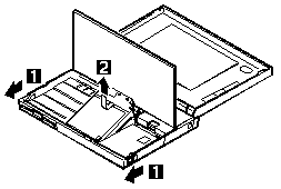
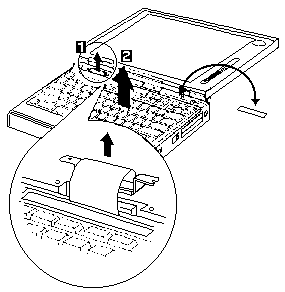
1070 Keyboard Unit #

This procedure and its drawings come from the ThinkPad 760 chapter of IBM's Volume 4 manual (vol4hmm, PDF page 269), not from a ThinkPad 770 manual. On the 770 the keyboard is removed as 1060 Keyboard Assembly; see PDF page 82 of the ThinkPad 770 Series HMM.

Note: When replacing the keyboard, affix the model number label.

Removing the keyboard unit, steps 1 and 2, with a close-up of the keyboard connector and the model number label shown at the right

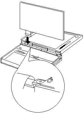
When replacing the keyboard unit, connect the keyboard connector as shown in the figure, then replace the keyboard.

Replacing the keyboard unit: the keyboard held upright while its connector is pressed into place, with a close-up inset

1040 Hard Disk Drive #

Source: ThinkPad 770 Series (9548, 9549) Hardware Maintenance Manual, p.79

IBM's drawing for this step is not reproduced on this page; see page 79 of the ThinkPad 770 Series HMM (PDF).

Attention Attention

Do not drop or apply any shock to the hard disk drive. The hard disk drive is sensitive to physical shock. Incorrect handling can cause damage and permanent loss of data on the hard disk.

Before removing the hard disk drive, have the user make a backup copy of all the information on the hard disk.

Never remove the hard disk drive while the system is operating or is in suspend mode.

Turn the computer upside down.

Step Size (Quantity) Color Torque (kgcm)
1 Coin screw (1)
—or—
Security screw (1)
Black —

Note: To remove the security screw, use a 2.5-mm allen wrench.

1060 Top Cover #

This procedure and its drawing come from the ThinkPad 760 chapter of IBM's Volume 4 manual (vol4hmm, PDF page 268), not from a ThinkPad 770 manual. The 770's removal sequence has no top-cover step; see PDF pages 76–119 of the ThinkPad 770 Series HMM.

  • Diskette Drive/CD-ROM Drive (Model Unique)
  • Battery Pack (760C/760L/760E/760EL)
  • Hard Disk Drive

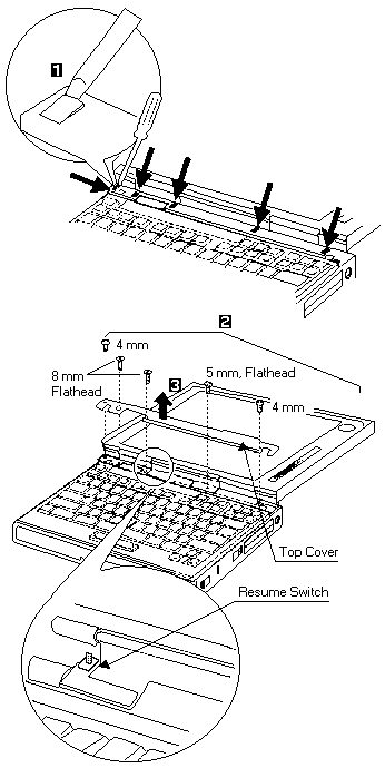
When replacing the top cover, be careful not damage the resume switch shown in the figure.

Removing the top cover, steps 1 to 3: prying it up at the arrowed points, removing the 4 mm screws and the 5 mm and 8 mm flathead screws, then lifting it off; an inset shows the resume switch

1075 Palm Rest #

This drawing comes from the ThinkPad 760 service material (in the 760 chapter of IBM's Volume 4 manual the palm rest is step 1160, vol4hmm, PDF page 294), not from a ThinkPad 770 manual. The 770's removal sequence has no palm-rest step.

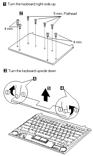
Removing the palm rest, steps 1 to 5: with the keyboard right-side up, removing the 4 mm and 5 mm flathead screws, then turning it upside down, releasing the two latches and lifting off the palm rest

ThinkPad - Common Parts Listing #

This section contains FRUs common to most IBM portable, laptop, and notebook computers.

External Diskette Drives

Part FRU P/N
5.25-Inch Diskette Drives:
360KB External (4869-001) 72X6759
360KB External (4869-501) 72X6768
1.2MB External (4869-002) 15X7993
1.2MB External (4869-502) 15X7994
Hard Disk Drive. 1.2GB HDD (for all 9545) 85G8549
5.25-Inch Drive Adapter 72X6757
5.25-Inch Drive Adapter/A 15F7996
5.25-Inch External Diskette Drive Cable (from system board to adapter) 27F4211
Diskette Drive Bus Adapter 72X8524

CD-ROM Drives

Part FRU P/N
Enhanced Internal CD-ROM II Drive (Eject button below slot) 61G1901
Internal CD-ROM I Drive (Eject button above slot) 81F7930
Terminator Kit (for 81F7930) 59F3530
Cleaning Kit (for 81F7930) (Disks, CD Caddy) 59F3562
Internal CD-ROM II Drive (Eject button below slot) 92F0084
Terminator Kit (for 92F0084) 92F0082
Media Kit (for 92F0084) (No cleaning necessary, Test Disk, CD Caddy) 31F4232
Signal Cable 34F0043
Power Cable 72X8521
Remote ID Switch Cable (3510) 92F0086
Audio Card, Cable, Screws (3510) 92F0085
CD Caddy 22F9419
Rail Kit (3510) 34F0041
Headphones 53F3610

SCSI Adapters, Terminators, Cables

Part FRU P/N
SCSI Adapter/A (without Cache) 85F0002
SCSI Internal Cable 64F4127
SCSI Adapter/A (with Cache) 85F0063
Terminator, External (for 85F0063) 33F8464
Terminator, Internal (for 85F0063) 34F0025
Terminator, Internal (for 85F0002) 57F2870
SCSI Fast Adapter (16 bit) 92F0330
SCSI External Cable (for 92F0330) 32G4089
SCSI Internal Cable (for 92F0330) 32G0084
Terminator, Inline (space permitting) 92F0412

Rewritable Optical Drives

Part FRU P/N
3.5-Inch Rewritable Optical Drive 92F0167
Rewritable Optical Cartridge 38F8647
Rewritable Optical Cartridge (5 Pack) 38F8646
Drive Mounting Slide (for 92F0167) 85F0022
Tray with Bezel (for 92F0167) 85F0021
Objective Lens Cleaner (for 92F0167) 38F8681
Prism Lens Cleaner (for 92F0167) 38F8682
3.5-Inch Enhanced Rewritable Optical Drive 92F0167
Mounting Tray 92F0269
Mounting Tray/Bezel (Model 3510) 92F0268

External Keyboard/Mouse

Part FRU P/N
Keyboard Cable 72X8537
Mouse 61X8923
Mouse Ball and Pop-Off Retainer 33F8461
Mouse Ball and Twist-Off Retainer 33F8462
Mouse (New Style) (33G5420) 06H4595
Mouse Retainer Ring 33G5417
Miniature Mouse 95F5723

Enhanced Keyboards (101/102 Key)

Country FRU P/N
Arabic 1391490
Belgian 1391414
Canadian French 1392011
Cyrillic 1393866
Danish 1391407
Dutch 1391511
French 1391402
German 1391403
Greek 1393285
Hebrew 1391408
Italian 1393395
Latin American Spanish 1392015
Norwegian 1391409
Portuguese 1391410
Russian/Cyrillic 1395622
Spanish 1391405
Swedish/Finnish 1391411
Swiss 1391412
Swiss/French 1395881
Swiss/German 1395882
Turkish 1393286
U.K. English 1391406
U.S. English (E/ME/A use only) 1396790
U.S. English 1392090
Yugoslavian 1393669

Optional Enhanced Keyboards (101/102 Key)

Part FRU P/N
with PS/2 Style Cable 59G7980
with AT Style Cable 59G7981
with 25mm PS/2 Trackball 59G7982
with 25mm Serial Trackball 59G9757

Keybutton Kits (101/102 Key)

Part FRU P/N
Keybutton Kits (R), Belgian 1392033
Keybutton Kits (R), Canadian French 1392032
Keybutton Kits (R), Danish 1392026
Keybutton Kits (R), Dutch 1392034
Keybutton Kits (R), French 6447047
Keybutton Kits (R), German 6447048
Keybutton Kits (R), Italian 6447049
Keybutton Kits (R), Norwegian 1392028
Keybutton Kits (R), Portuguese 1392029
Keybutton Kits (R), Spanish 6447050
Keybutton Kits (R), Spanish / Latin 1392035
Keybutton Kits (R), Swedish 1392030
Keybutton Kits (R), Swiss / French / German 1392031
Keybutton Kits (R), U.K. English 6447046
Keybutton Kits, U.S. English 6447045

Japanese Keyboard Type 2 (106 Key, DBCS Support)

Part FRU P/N
Japanese Keyboard 94X1110
Keyboard Cable 94X1147

Space-Saving Keyboards (84/85 Key)

Part FRU P/N
Canadian French 1396046
Spanish/Latin 1396047
U.S. English 1393290
Cable Assembly, External 1393082

Tools and Miscellaneous

Part FRU P/N
Audio Wrap Cable 66G5180
Ethernet BNC T-Connector 84F8207
Ethernet BNC 50-ohm Terminator (2 required) 85F0037
Grounding Wire Set 38F4684
Keyboard Key Cap Removal Tool 6110464
PC Test Card 33G4703
Screwdriver Kit 95F3598
SCSI Terminator (any SCSI device, space permitting) 92F0142
SCSI Terminator Kit (R-PAC Terminator Modules (3) for 40, 60, 80, 120, and 160MB SCSI Hard Disk Drives) 92F0143
Wrap Plug Ethernet D-Shell 85F0036
Wrap Plug, Tri-Connector 72X8546
Wrap Plug (6157 Tape Attachment Adapter/A) 4178459
Wrap Plug (Token-Ring Network Adapter/A) 6165899
Plastic Envelope (For Wrap Plug) 6138013

TV Tuner #

The TV Tuner Pack (hereafter called TV Tuner) is an option for watching TV programs or videos on the IBM TFT color notebook computer. The computer changes to TV reception when the removable diskette drive is replaced with the TV Tuner.

The TV screen and normal computer display are easily switched by using the Hot key on the front panel of the TV Tuner.

Identifying Names and Functions

The following figure and table show the names and functions of each part of the TV Tuner.

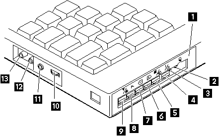
TV Tuner, showing the front panel controls and the side jacks and connectors numbered 1 to 13

IconsFunctions
1 Front PanelUsed to change the TV channels, switch TV mode to computer mode, and operate most functions of the TV Tuner.
2 Headphone Jack
Headphone jack
Connects the headphones.
3 Power IndicatorShows the TV Tuner is powered on.
4 Power Switch
Power switch
Powered on and off the TV Tuner.
5 Hot Key
Hot key
Switches between the TV screen and computer screen.
6 Up Switch
Up switch
Increases the value such as the channel number.
7 Down Switch
Down switch
Decreases the value such as the channel number.
8 Function Key
Fn key
Enters the mode to change the value of each function, such as TV channel or color contrast. (See Using the Function Key.)
9 TV/EXT Switch
TV/EXT button
Switches the TV mode or external video mode.
10 Volume Knob
Volume knob
Controls the speaker volume.
11 Audio-In Jack
Audio-in jack
Connects the audio-in connector of the AV cable.
12 Video-In Jack
Video-in jack
Connects video-in connector of the AV cable.
13 RF Connector
RF (antenna) connector
Connects the active antenna unit or antenna cable.

Using the Front Panel

The following table shows how to operate all functions of the TV Tuner with the controls on the front panel.

KeyFunction
Power
Power switch
Turns on the TV Tuner. This key is used only when the computer is turned on.
Hot Key
Hot key
Switches computer display and TV screen.
Up
Up switch
Increases the value of parameters, Channel Number, Color, Tint, Brightness, Contrast, Auto Tuning Sensitivity, On-screen Message Selection.
Down
Down switch
Decreases the value of parameters, Channel Number, Color, Tint, Brightness, Contrast, Auto Tuning Sensitivity, On-screen Message Selection.
Function
Fn key
Selects a function mode to adjust each function parameter. (See Using the Function Key.)
TV/Ext
TV/EXT button
Switches the displayed video source between the receiving TV broadcast program and external devices such as VCR, video camera recorder, laser disk, and so on.

Diskette Drive (Model Unique) #

This procedure and its drawing come from the ThinkPad 760 chapter of IBM's Volume 4 manual (vol4hmm, PDF page 260). On the ThinkPad 770 the diskette drive sits in the UltraBay II; see PDF page 77 of the ThinkPad 770 Series HMM.

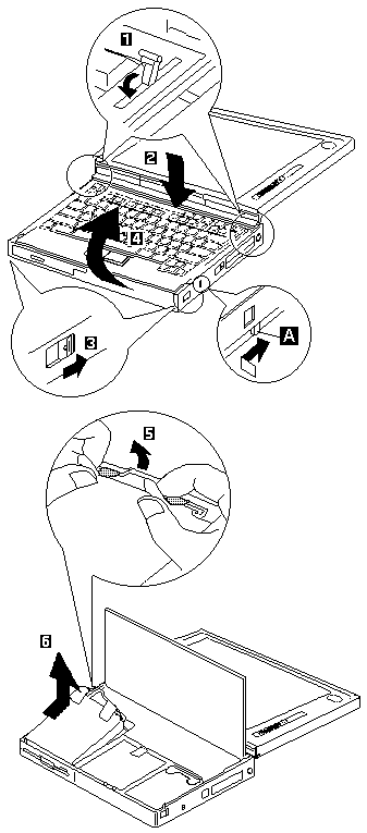
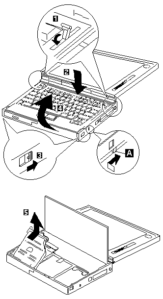
Note: If the security latch A is at the left position, push and slide it to the right position (unlock).

Removing the diskette drive: releasing and raising the keyboard (steps 1 to 4), then pulling up the drive strap (5) and lifting the drive out (6); inset A shows the security latch

CD-ROM Drive (Model Unique) #

This procedure and its drawing come from the ThinkPad 760 chapter of IBM's Volume 4 manual (vol4hmm, PDF page 261). On the ThinkPad 770 the CD-ROM drive sits in the UltraBay II; see PDF page 77 of the ThinkPad 770 Series HMM.

Attention Attention: Remove the CD-ROM drive exactly as shown in the figure. Do not apply any extra force to the CD-ROM drive when removing it.

Note: If the security latch A is at the left position, push and slide it to the right position (unlock).

Removing the CD-ROM drive: releasing and raising the keyboard (steps 1 to 4), then lifting the drive straight out (5); inset A shows the security latch