Pre-ThinkPad IBM Portables

IBM PS/2 CL57 SX

Machine Type 8554 · 1991 · 29 sections

A 20 MHz 386SX Micro Channel portable with a 10.4-inch active-matrix colour screen, a built-in trackball and two NiMH battery packs. The service notes below follow the CL57 chapter of IBM's Mobile Systems Hardware Maintenance Manual, Volume 1.

This is a transcribed historical service reference and may contain incomplete captures. Consult the linked original manuals as the authoritative sources before servicing.

Service Reference

Product Overview #

Compiled from a hardware survey and IBM's product records. A dash means no source records the value.

PS/2 CL57 SX specifications
Specification PS/2 CL57 SX
Released March 1992
Processor
  • Intel 386SX, 20 MHz
  • 387 coprocessor support
Bus Micro Channel
Memory Standard 2 MB; maximum 16 MB; IC DRAM card (parity)
Storage 2.5" ESDI: 80 MB
Display 10.4" active matrix, 640 × 480
Graphics 256 KB video memory
Audio PC speaker
Main battery
  • NiMH
  • External rechargeable pack (optional)
Power connector Proprietary 4-pin
Media drives 3.5" 1.44 MB floppy drive
PC Card slots None
Networking Modem (optional)
Ports
  • Parallel
  • Serial
  • VGA out
  • PS/2
  • Micro Channel expansion bus port
BIOS IBM BIOS
Pointing device Trackball

General Checkout #

Source: Hardware Maintenance Manual Volume 1: Laptop, Notebook, Portable and ThinkPad Computers, p.124

Start here when the CL57 SX does not start or work correctly. Work through the numbered steps in order and, where a step asks a question, follow its Yes or No branch.

001

Does the problem appear to be a power supply failure?

Yes — go to Step 003. No — go to Step 002.

002

Go to Step 006.

003

Do all system-status indicators remain off?

Yes — go to Step 005. No — go to Step 004.

004

Go to Step 006.

005
006
  • Power-off the computer and all external devices.
  • Check all cables and power cords.
  • Make sure no diskette is in the drive.
  • Power-on all external devices.
  • Power-on the computer and check for the following responses:
    1. All system-status indicators appear once for about 1 second.

      Note: Some indicators remain on and others go off after 1 second.

    2. Memory test (the number increases.)
    3. Audible responses:
      One short beep
      - or -
      Two short beeps.

Did you receive the responses listed above?

Yes — go to Step 008. No — go to Step 007.

007

Go to Step 013.

008
  • Press Ctrl+Alt+Del. When the cursor moves to the upper right, press Ctrl+Alt+Ins to start the system program. If the IBM logo screen does not appear, insert the backup Reference Diskette into the diskette drive and repeat this step.
  1. If you are not at the Main Menu, follow the instructions on the screen to advance to the Main Menu.

    If you cannot advance to the Main Menu, go to Symptom-to-FRU Index.
    - or -
    If that does not correct the problem, go to Undetermined Problem.

    Notes:

    1. If the computer has an incorrect keyboard or numeric keypad response, go to External Keyboard/Auxiliary Input Device Checkout.
    2. If the printer has incorrect responses, go to Printer Checkout.
    3. If the external CRT display has problems such as jittering, rolling, shifting, or being out-of-focus, go to External Display Self-Test.
  2. Press Ctrl+A and run the system checkout.

Is the list of installed devices correct?

Yes — go to Step 010. No — go to Step 009.

010
  • Run the diagnostic tests.

Did the test identify a failure?

Note: If the test stops and you cannot continue, replace the last device tested.
- or -
If any POST error code appears, go to Symptom-to-FRU Index.

Yes — go to Step 012. No — go to Step 011.

011

You might have an intermittent problem:

  • Check for damaged cables and connectors.
  • Reseat all adapters, drives, and modules.
  • Start an error log and run the tests multiple times.
  • Check the power supply in use when the error is reported (see Power Systems Checkout).
  • Check Symptom-to-FRU Index. If this did not fix the problem, go to Undetermined Problem.
013

Did nothing appear on the screen?

Yes — go to Step 015. No — go to Step 014.

014
015

Go to Symptom-to-FRU Index.
- or -
If that does not correct the problem, go to Undetermined Problem.

Printer Checkout #

Source: Hardware Maintenance Manual Volume 1: Laptop, Notebook, Portable and ThinkPad Computers, p.480

  1. Make sure the printer is correctly connected and is powered-on.
  2. Run the printer self-test.

If the printer self-test does not run correctly, the problem is in the printer. Refer to the printer service manual.

If the printer self-test runs correctly, do the following.

  1. Verify the port settings in configuration.
  2. Install a wrap plug on the port (indicated in configuration) and run the advanced diagnostic tests.
  3. If the advanced diagnostic tests (with the wrap plug installed) do not detect a failure, replace the printer cable. If the problem is not corrected, replace the system board.

Fax/Modem Checkout #

Source: Hardware Maintenance Manual Volume 1: Laptop, Notebook, Portable and ThinkPad Computers, p.478

001
  • Power-off the computer.
  • Ensure that the modem is installed correctly.
  • If the modem never worked in customer mode, ensure that all drivers are loaded correctly onto the computer.
  • Ensure that the communication program is supported on the computer.
  • Ensure that the public switch telephone network (PSTN) cable and the data access arrangement (DAA) cable, if installed, are connected correctly.

If you need to correct one of the above conditions, do so now; then continue.

Note: PCMCIA cards can be inserted and removed while the system is powered on.

  • Power-on the system.
  • Insert the IBM Data/FAX Modem diskette into the default diskette drive.
  • If you are servicing a High Speed Internal Data/Fax Modem (Models FC3632 and FC3650), at the DOS prompt (for example, A:\), type IBMDIAG; then press Enter.
  • If you are servicing a PCMCIA Data/FAX Modem (Models FC3634 and FC3635), at the DOS prompt (for example, A:\), type ESTDIAG; then press Enter.
  • Follow the instructions on the screen. (If you need help, press F1.)

Did the diagnostic tests detect an error?

Yes — go to Step 003. No — go to Step 002.

002

The diagnostic tests have completed successfully. If you suspect a problem, go to Step 004.

003

Go to the Symptom-to-FRU Index for the computer you are servicing.

004
  • Check the PSTN cable and the DAA cable, if installed, for continuity.

Is the cable(s) good?

Yes — go to Step 006. No — go to Step 005.

005

Replace the defective cable(s).

006
  • Have the customer transmit a call.

Was the call transmitted successfully?

Yes — go to Step 008. No — go to Step 007.

007

Go to Step 011.

008
  • Have the customer receive an incoming call on the modem.

Was the incoming call received?

Yes — go to Step 010. No — go to Step 009.

009

Go to Step 014.

010

The diagnostic tests have completed successfully. If you still suspect a problem that is not software related, replace the External DAA; then replace the modem.

011
  • Have the customer transmit a call at a lower speed.

Was the call transmitted successfully?

Yes — go to Step 013. No — go to Step 012.

012

If installed, replace the external DAA. If you do not have an external DAA installed, or replacing the external DAA does not correct the problem, replace the modem.

013

Have the telephone line checked.

014
  • Have the customer receive an incoming call on the modem at a lower speed.

Was the incoming call received?

Yes — go to Step 016. No — go to Step 015.

015

If installed, replace the external DAA. If you do not have an external DAA installed, or replacing the external DAA does not correct the problem, replace the modem.

016

Have the telephone line checked.

External Keyboard / Auxiliary Input Device Checkout #

Source: Hardware Maintenance Manual Volume 1: Laptop, Notebook, Portable and ThinkPad Computers, p.477

The following auxiliary input devices may be available for IBM ThinkPad models.

  • Numeric keypad
  • Mouse (PS/2 compatible)
  • External keyboard (with Keyboard/Miniature Mouse cable)
  • If you suspect a problem with any of the auxiliary input devices (listed above), replace the device.

    If the problem is not corrected, replace the following FRUs one at a time to correct the problem.

    • Keyboard control card
    • System board
  • If the computer receives an incorrect keyboard response, remove other external devices, check the keyboard connections, and recheck the keyboard responses. If the problem remains, replace the following FRUs one at a time to correct the problem.

    • Keyboard
    • Keyboard control card
    • System board
  • If a 00030100 error message appears, power-off the computer and the external devices. Then power-on the computer before you power-on the external devices.

Memory Checkout #

Source: Hardware Maintenance Manual Volume 1: Laptop, Notebook, Portable and ThinkPad Computers, p.127

Customer diagnostics can eliminate defective memory so no memory error code appears at power-on reset. After you replace a defective memory module on the system board or IC DRAM card, run Automatic Configuration. Otherwise, the new memory will not be recognized. (If you have to run configuration with your own diskette, be sure the customer has all the correct option diskettes available.) Power-off the computer before removing or replacing parts.

001
  • Remove all IC DRAM cards from the slots if installed.
  • Run the memory tests.
    Use the RUN TESTS ONE TIME option.

Did the memory tests end without an error?

Yes — go to Step 003. No — go to Step 002.

002

Replace the memory module on the system board.

003

Did you remove the IC DRAM card from slot 1?

Yes — go to Step 005. No — go to Step 004.

004

Go to Step 007.

005
  • Reinstall the IC DRAM card into slot 1 and run Automatic Configuration.
  • Run the memory test.
    Use the RUN TESTS ONE TIME option.

Did the memory tests end without an error?

Yes — go to Step 007. No — go to Step 006.

006

Replace the IC DRAM card in slot 1.
If that does not correct the problem, replace the system board.

007

Did you remove the IC DRAM card from slot 1?

Yes — go to Step 009. No — go to Step 008.

008

Go to Step 011.

009
  • Reinstall the IC DRAM card into slot 2 and run Automatic Configuration.
  • Run the memory test.
    Use the RUN TESTS ONE TIME option.

Did the memory tests end without an error?

Yes — go to Step 011. No — go to Step 010.

010

Replace the IC DRAM card in slot 2.
If that does not correct the problem, replace the system board.

011

If the problem occurs intermittently, run the memory tests multiple times to have an error log.

Checking Installed Devices #

Source: Hardware Maintenance Manual Volume 1: Laptop, Notebook, Portable and ThinkPad Computers, p.143

The Installed Devices List shows the presence of devices in the computer. If an adapter or device is missing from the list, you might have one of the following conditions.

Attention Warning: A customized setup configuration (other than default settings) might exist on the computer you are servicing. Running Automatic Configuration can alter those settings. Note the current configuration settings (using the View configuration) and verify that the same settings are in place when service is complete.
  • The protected partition on the hard disk or the Reference Diskette you are using does not contain the code required to support that device.
  • An adapter or device is defective.
  • The device missing from the list is an unrecognizable drive or adapter.
  • The device missing from the list requires an additional diskette.
  • A power supply voltage is incorrect (see Power Systems Checkout).

If the adapter is on the list, run the adapter diagnostics tests. If the list contains an adapter or device that is not installed, go to Undetermined Problem.

Power Systems Checkout #

Source: Hardware Maintenance Manual Volume 1: Laptop, Notebook, Portable and ThinkPad Computers, p.129

Note: One or all of the batteries can discharge if there is a short circuit in the computer.

  1. Replace the failing FRU if the power supply problem is caused by a short circuit.
  2. Determine if one (or all) of the batteries have become discharged. Replace a discharged battery with a known-good spare.
  3. Observe the Battery ID indicators or swap the two battery packs to determine which one has become discharged.

The test procedures for each power supply are found on the following pages.

None of the above? Follow the steps below.

001

Did the problem occur only when using the AC adapter?

Yes — go to Step 003. No — go to Step 002.

002

Go to Step 004.

003

Go to Testing the AC Adapter. If that does not correct the problem, replace the voltage converter.

004

Did the problem occur only on battery powered operation?

Yes — go to Step 006. No — go to Step 005.

005

Go to Step 007.

006
  • Make sure the battery packs are fully charged.
  • Go to Testing the Battery Pack and check the battery packs. If that does not correct the problem, replace the voltage converter.
007

Do all system status indicators remain off after power on?

Yes — go to Step 009. No — go to Step 008.

008

Go to Step 016.

009
  • Remove the following if installed:
    • Battery packs
    • Backup battery
    • IC DRAM card
    • Internal Data/Fax modem
    • Serial adapter
    • Numeric keypad
    • Math coprocessor
    • Mouse
    • External display
  • Go to Step 010.
010
  • Plug in the AC adapter and power-on the computer.

Does any indicator remain on?

Yes — go to Step 012. No — go to Step 011.

011
  • Power-off the computer and remove the following.
    • Hard disk drive
    • Diskette drive
    • LCD cables
    • Keyboard flexible cables
  • Power-on the computer again.
  • Go to Step 013.
012

Suspect one of the options or devices.

  • Reinstall each of the options or devices to the computer one at a time, and power-on the computer to see if the original problem occurs.
  • Replace the last installed option or device when the problem occurs.
013

Does any indicator remain on?

Yes — go to Step 015. No — go to Step 014.

014
  • Replace the following FRUs one at a time until the problem is corrected.
    • Indicator card
    • System board
    • Voltage converter
015

Suspect one of the devices.

  • Reinstall each of the devices to the computer one at a time, and power-on the computer to see if the original problem occurs.
  • Replace the last installed device when the problem occurs.
016
  • Observe the system-status indicators for about 1 second after power on.
System-Status Indicator Condition A Condition B
Power-OnOffOn
Suspend ModeOffOn
Scroll LockOnOff
Caps LockOnOff
Numeric LockOnOff
Diskette DriveOnOff
Hard Disk DriveOnOff
Battery ID 2OffOn
Battery Status 2OffOn
Battery ID 1OffOn
Battery Status 1OffOn
Carrier Detect––

If the status lights match either condition A or B, replace the voltage converter. If the status lights are different from condition A or B, or replacing the voltage converter does not correct the problem, go to Undetermined Problem.

Testing the AC Adapter #

If the Power-On indicator is not on, check the power cord of the AC adapter for proper installation and continuity.

  1. If any noise can be heard from the AC adapter when it is plugged into line voltage, replace the AC adapter with a new one.

    If no noise can be heard from the adapter, go to Step 3.

  2. If the noise still comes from the new AC adapter, suspect the computer. Replace the AC adapter with the original one, then go to the next step. If no noise comes from the new adapter, the original adapter has the problem.
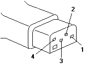
  3. Unplug the AC adapter cable from the computer and measure the output voltages at the plug of the AC adapter cable. Connect the minus lead of the volt-ohm meter to pin 3 during the measurement.

    Plug of the AC adapter cable with its pins numbered 1 to 4 for voltage measurement

    Pin Voltage (V dc)
    1+18 to +22
    2+17 to +21
    3GND
    4Communication GND
  • If the voltages are not correct:
    1. Unplug the AC adapter from the ac power outlet and leave it for a few minutes.
    2. Plug the AC adapter into the ac outlet.
    3. Measure the output voltages of the AC adapter.
    4. If the voltages are still not correct, replace the AC adapter.
  • If the voltages are OK, plug the cable into the computer and try the failing operation again.

If the problem still remains, replace the voltage converter. If the problem disappeared, suspect the installation and continuity of the AC adapter cable.

Testing the Battery Pack #

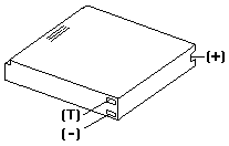
  1. Remove each battery pack and measure the voltage at the battery terminals between (+) and (−).

    Battery pack with its (+), (T) thermal-detection and (-) terminals labelled for voltage measurement

    Terminal Voltage (V dc)
    (+)+12 to +18
    (T)Thermal Detection
    (−)Ground
    • If the voltage is less than +12 V dc, the battery pack is discharged or defective.
    • If the voltage is more than +12 V dc, go to the next step.
  2. Using a low-power ohm meter, measure the resistance at the battery terminals between (T) and (−). The resistance must be 500 ohms to 20 kilohms.

    If the resistance is out of range, replace the battery pack.

Testing the Backup Battery #

  1. Remove the keyboard and the top cover.
  2. Disconnect the battery connector from the system board.
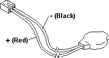
  3. Measure the voltage of the backup battery.

    Backup battery and its cable connector, with the + (red) and - (black) wires labelled for voltage measurement

    Wire Voltage (V dc)
    Red+2.5 to +3.7
    BlackGround

If the voltage is correct, replace the system board. If it is not, the backup battery is discharged by a short circuit or is defective.

How to Run the Diagnostics #

  1. Power-on the computer.
  2. When the cursor moves to the upper right, press Ctrl+Alt+Ins to start the system program. If the IBM logo does not appear, insert the backup copy of the Reference Diskette into the diskette drive, press Ctrl+Alt+Del, then repeat this step.
  3. Advance to the Main Menu.
  4. Press Ctrl+A to run the system checkout.

External Display Self-Test #

Source: Hardware Maintenance Manual Volume 1: Laptop, Notebook, Portable and ThinkPad Computers, p.476

If the display problem occurs only when using an external display, use the following instructions to correct the problem.

Note: Before you replace a display, check the following list to see if it is connected correctly.

  • 8506 and 8508 displays must be connected to an Image Adapter/A or an Image-I Adapter/A.
  • 63XX and 85XX systems support either 63XX or 85XX displays.
  • 85XX systems with an XGA-2 adapter support 95XX displays.
  • 95XX systems support either 63XX, 85XX, or 95XX displays.
  • ThinkPad models support either 85XX or 95XX displays.

If the screen is rolling, replace the display assembly. If that does not correct the problem, replace FRUs in the following order until the problem goes away:

  1. Video card
  2. Display adapter (any type)
  3. System board
  4. Bus adapter (if used)

If the screen is not rolling, run the display self-test as follows:

  1. Power-off the computer and display.
  2. Disconnect the display signal cable.
  3. Power-on the display.
  4. Set the contrast to its maximum position.
  5. Set the brightness control to the center detent position.

Check for the following conditions:

  • You should be able to vary the screen intensity by adjusting the contrast and brightness controls.
  • The screen should be white or light gray, with a black margin (test margin) on the screen.

    Note: The location of the test margin varies with the type of display. The test margin might be on the top, bottom, or one or both sides.

If you do not see a test margin on the screen, replace the display. If there is a test margin on the screen, replace the system board.

Note: On ThinkPad Models 700, 700C, 720C, 720C, do the following:

  1. Video card
  2. System board

Symptom-to-FRU Index #

Source: Hardware Maintenance Manual Volume 1: Laptop, Notebook, Portable and ThinkPad Computers, p.134

The Symptom-to-FRU Index lists error symptoms and possible causes. The most likely cause is listed first. Always begin with General Checkout. This index also can be used to help you decide which FRUs to have available when servicing a computer.

If you are unable to correct the problem using this index, go to Undetermined Problem.

Attention IMPORTANT:

  1. If you have both an error message and an incorrect audio response, diagnose the error message first.
  2. If you cannot run the advanced diagnostics tests, but did receive a POST error message, diagnose the POST error message.
  3. If you did not receive an error message, look for a description of your error symptoms in the first part of this index.
  4. Check all power supply voltages before you replace the system board. (See Power Systems Checkout.)
  5. If an error message is not listed, there is a device installed that requires an additional diskette or service manual. Refer to the diskette or service manual for that device.

How to Read POST Error Messages

POST error messages are displayed on the screen as 3, 4, 5, or 8 digits. The error messages that can be displayed as shorter POST messages are highlighted in this Symptom-to-FRU Index.

Miscellaneous Symptoms #

Source: Hardware Maintenance Manual Volume 1: Laptop, Notebook, Portable and ThinkPad Computers, p.139

Note: A no beep symptom can be caused by incorrect volume setting of the speaker. Set the speaker volume to its maximum position.

Symptom/Error FRU/Action
A no beep and a blank or unreadable display during POST. (See Power Systems Checkout before replacing any FRUs.)
  1. System Board
  2. Voltage Converter
  3. Communications Cartridge
  4. Hard Disk Drive
  5. Display Control Card
  6. Any options
  7. Power source when failing
A no beep with a blinking cursor.
  1. System Board
  2. Display Control Card
  3. Communications Cartridge
A no beep with a normal display during POST.
  1. Speaker
  2. Indicator Card
  3. System Board
  4. Keyboard Control Card
A no beep and the computer hangs after displaying memory count.
  1. System Board
  2. Communications Cartridge
  3. Hard Disk Drive
LCD too dark, unable to adjust contrast or brightness. (See CL57 LCD FRU Replacement Notice before replacing any FRUs.)
  1. LCD Panel
  2. Regulator
  3. Voltage Converter
LCD unreadable or illegible. (See CL57 LCD FRU Replacement Notice before replacing any FRUs.)
  1. LCD Panel
  2. Display Control Card
  3. LCD Cable
Missing or discolored dots on the LCD panel.
  1. See CL57 LCD FRU Replacement Notice
Unable to turn the LCD on and off.
  1. Regulator
  2. Voltage Converter
  3. LCD Cable
Blank screen, or extra horizontal or vertical line(s) displayed on upper or lower half of the LCD. (See CL57 LCD FRU Replacement Notice before replacing any FRUs.)
  1. LCD Panel
  2. Display Control Card
  3. LCD Cable

Four battery indicators are blinking.

  • Battery ID 1
  • Battery Status 1
  • Battery ID 2
  • Battery Status 2
  1. Voltage Converter
  2. System Board
System status indicator is incorrectly blinking or stays on.
  1. Related Device
  2. System Board
  3. Indicator Card
System status indicator stays off, but the POST ends without an error.
  1. Indicator Card
  2. System Board
  3. Related Device
Reference Diskette does not work. (Try another Reference Diskette or any bootable diskette before replacing FRUs. Ensure all correct level drivers are loaded.)
  1. Diskette Drive
  2. System Board
  3. Diskette Drive Cable
  4. Reference Diskette
Keyboard does not work.
  1. Keyboard Control Card
  2. Keyboard Cable
  3. Numeric Keypad if used
  4. System Board
One or more keys do not work. (See External Keyboard/Auxiliary Input Device Checkout before replacing any FRUs.)
  1. Keyboard
  2. Numeric Keypad
  3. Keyboard Control Card
External display problems. (See External Display Self-Test before replacing any FRUs.)
  1. External Display
  2. Display Control Card
Incorrect memory size during POST. (See Memory Checkout before replacing any FRUs.)
  1. System Board
  2. Memory Module
  3. IC DRAM Card
Computer hang or Intermittent hang. (See Undetermined Problem before replacing any FRUs.)
  1. System Board
  2. Hard Disk Drive Cable
  3. Hard Disk Drive
  4. Replace the last device being tested
  5. Display Control Card
  6. Memory Module
  7. IC DRAM Card
  8. Voltage Converter
The computer goes into suspend mode after the POST.
  1. System Board
  2. Voltage Converter
  3. Lid Switch
  4. Keyboard Control Card
The computer does not suspend or resume.
  1. System Board
  2. Voltage Converter
  3. Lid Switch
  4. Keyboard Control Card
The computer does not power off.
  1. Voltage Converter
  2. System Board
  3. Indicator Card
Real-time clock inaccurate. (See Testing the Backup Battery before replacing any FRUs.)
  1. Backup Battery
  2. System Board
Printer problems.
  1. See Printer Checkout
Serial or parallel port device problems.
  1. Device
  2. Cable
  3. System Board
  4. Serial Adapter (if attached)
  5. I/O Panel Assembly
Internal Data/Fax modem does not communicate with a remote modem or a fax.
  1. See Fax/Modem Checkout

Undetermined Problems #

You are here because the diagnostics tests did not identify the failing FRU.

Check the power supply in use (see Power Systems Checkout). If the power supply is operating correctly, return here and continue with the following procedure.

  1. Power-off the computer and remove the battery packs from the computer.
  2. Remove or disconnect one of the following devices or adapter (do not isolate FRUs that are known to be good).
    1. Non-IBM devices
    2. Modem, printer, mouse, or other external device
    3. IC DRAM card
    4. Hard disk drive (fixed disk drive) or diskette drive
    5. Communications cartridge
    6. Any adapter and device
  3. Power-on the computer and start the system program.
  4. Press Ctrl+A to run the system checkout. Do not configure the computer. If diagnostics cannot be loaded from the hard disk, try and load them from the Reference Diskette. Test only those adapters and devices still attached to the computer.
  5. If the symptom remains, repeat steps 1 through 3 until you find the failing FRU or until all FRUs have been removed.
  6. If all of the FRUs listed have been removed and the problem remains, replace the system board.

Numeric Error Codes #

Source: Hardware Maintenance Manual Volume 1: Laptop, Notebook, Portable and ThinkPad Computers, p.135

In the following index, an X in an error message can be any number.

Symptom/Error FRU/Action
00010200, 00010300, 00010400, 00010700
  1. System Board
00010800
  1. System Board
  2. Communications Cartridge
00011000 (See Memory Checkout before replacing any FRUs.)
  1. IC DRAM Card or Memory Module
  2. System Board
000110XX
  1. IC DRAM Card or Memory Module
  2. System Board
000113XX
  1. System Board
  2. Communications Cartridge
  3. Any Drive
000114XX
  1. Communications Cartridge
000118XX
  1. IC DRAM Card or Memory Module
  2. System Board
00016100
  1. See Testing the Backup Battery
  2. System Board
  3. Voltage Converter
00016300, 00016400, 00016500, 00016900 (If setting configuration does not solve the problem, see Checking Installed Devices.)
  1. Set Configuration
  2. System Board
  3. Communications Cartridge
  4. Hard Disk Drive
  5. IC DRAM Card
  6. Memory Module
000166XX
  1. Communications Cartridge
000171XX
  1. See Testing the Backup Battery
  2. System Board
000172XX
  1. System Board
00017300
  1. See Testing the Backup Battery
  2. System Board
  3. Voltage Converter
00017400 (If Automatic Configuration does not solve the problem, run Advanced Diagnostics.)
  1. Set Configuration
  2. System Board
  3. Math Coprocessor
00019000, 000191XX
  1. System Board
00019200
  1. Lid Switch
  2. Keyboard Control Card
  3. System Board
00019300
  1. System Board
000199XX
  1. System Board
0001XXXX (not listed above)
  1. System Board
  2. Communications Cartridge
  3. Indicator Card
0002XXXX (See Memory Checkout before replacing any FRUs.)
  1. IC DRAM Card or Memory Module
  2. System Board
00030100, 00030500
  1. Keyboard Control Card
  2. System Board
  3. Keyboard or Numeric Keypad
00030200, 00030300, 00030400
  1. System Board
  2. Keyboard Control Card
  3. Keyboard or Numeric Keypad
00030600
  1. Keyboard or Numeric Keypad
  2. Auxiliary Input Device
  3. Keyboard Control Card
  4. System Board
  5. I/O Panel Assembly
0004XXXX
  1. System Board
  2. Any Parallel Device
  3. Communication Cable
  4. I/O Panel Assembly
000601XX
  1. Diskette Drive
  2. System Board
  3. Diskette Drive Cable
000602XX
  1. Defective Diskette
000655XX, 000662XX 000670XX to 000675XX
  1. System Board
  2. Diskette Drive
  3. Diskette Drive Cable
0006XXXX Unsupported drive or cable.
  1. Diskette Drive
  2. System Board
  3. Diskette Drive Cable
000720XX
  1. System Board
  2. Math Coprocessor
0007XXXX
  1. Math Coprocessor
  2. System Board
0011XX00
  1. System Board
  2. Serial Connector
  3. Any Serial Device
  4. Communication Cable
0014XXXX (See Printer Checkout before replacing any FRUs.)
  1. Printer
  2. System Board
0024XX00
  1. Display Control Card
  2. Voltage Converter
005002XX, 005006XX, 005008XX
  1. Display Control Card
  2. Voltage Converter
  3. External Display
  4. I/O Panel Assembly
005004XX, 005010XX, 005032XX
  1. Display Control Card
  2. LCD Panel
  3. LCD Cable
005009XX
  1. External Display
  2. Display Control Card
  3. I/O Panel Assembly
00860100, 00860200 00861700, 00861800
  1. Mouse or Trackball
  2. System Board
  3. Numeric Keypad
  4. I/O Panel Assembly
0086XX00
  1. System Board
  2. Mouse or Trackball
  3. Numeric Keypad
  4. I/O Panel Assembly
0101XXXX
  1. See Fax/Modem Checkout
010436XX
  1. System Board
  2. Hard Disk Drive
  3. Hard Disk Drive Cable
0104XXXX
  1. Hard Disk Drive
  2. System Board
  3. Hard Disk Drive Cable
0130XXXX
  1. Indicator Card
  2. System Board
  3. Keyboard Control Card
0137XXXX
  1. Serial Adapter
  2. System Board
  3. Communication Adapter Holder
  4. Any Serial Device
  5. Communication Cable
0166XXXX, 0167XXXX
  1. Adapter in Communications Cartridge
  2. Communications Cartridge
I9990301 (Startup drive not found.)
  1. Start the backup copy of the Reference Diskette and verify if the startup sequence is correct.
    1. Select Set features from the Main Menu.
    2. Select Set startup sequence.
    3. Check the list of devices on the screen.
I9990302 (Operating system not found.)
  1. Make sure that an operating system is installed.
  2. Hard Disk Drive
  3. System Board
  4. Hard Disk Drive Cable
I998XXXX, I9990303 (See Hard Disk Partition before replacing any FRUs.)
  1. Restore the system programs onto the system partition.
  2. Set configuration
  3. Hard Disk Drive
  4. System Board
  5. Hard Disk Drive Cable

Beep Symptoms #

Source: Hardware Maintenance Manual Volume 1: Laptop, Notebook, Portable and ThinkPad Computers, p.139

Symptom/Error FRU/Action
Continuous beep.
  1. System Board
Repeating short beeps. (See External Keyboard/Auxiliary Input Device Checkout before replacing any FRUs.)
  1. Keyboard
  2. Keyboard Control Card
  3. System Board
One long and one short beep.
  1. System Board
One long and two short beeps.
  1. Display Control Card
  2. System Board
One short beep and a blank, unreadable, or flashing display with no external display attached. (See CL57 LCD FRU Replacement Notice before replacing any FRUs.)
  1. LCD Panel
  2. Display Control Card
  3. System Board
  4. LCD Cable
One short beep and Diskette Prompt or a program load from the hard disk or unable to read diskette.
  1. Diskette Drive
  2. System Board
  3. Diskette Drive Cable
Two short beeps and a blank display.
  1. System Board

CL57 LCD FRU Replacement Notice #

Source: Hardware Maintenance Manual Volume 1: Laptop, Notebook, Portable and ThinkPad Computers, p.145

If missing or discolored dots appear on the LCD, carefully read the following note to determine whether you should replace the LCD.

Attention Important

The LCD for the Model CL57 contains over 921 000 thin film transistors (TFTs). A small number of missing, discolored or lighted dots (on all the time) is characteristic of TFT LCD technology, but excessive pixel problems can cause viewing concerns. The LCD should be replaced if the number of dots satisfies either of the following conditions:

  • The number of missing or discolored dots in any colored back ground, except black, is 14 or more.
  • The number of lighted dots in a black background is 7 or more.

FRU Removals and Replacements #

Source: Hardware Maintenance Manual Volume 1: Laptop, Notebook, Portable and ThinkPad Computers, p.147

Removals and replacements

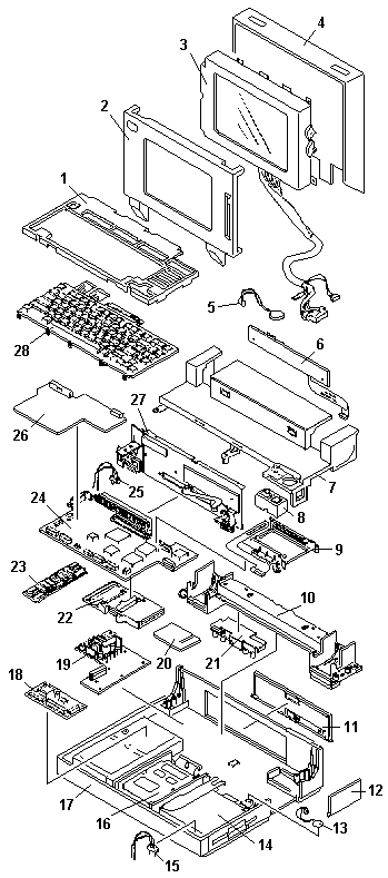
The numbers in this list match the callouts in IBM's exploded view of the CL57 SX, which is not reproduced here; see PDF pages 150–151 of the manual. Indented entries without a number are disconnected or removed as part of the numbered step above them.

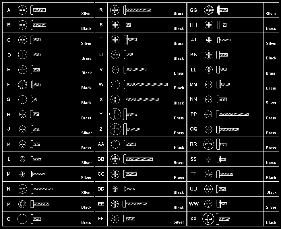
Follow the numerical sequence in the FRU removal sequence list and the exploded view to remove or disconnect parts in the correct order. The letters in parentheses in the list indicate screw types. See the Screw Size Chart to match the letters to the correct screw type and size before replacing each screw.

Warning Safety Notice 8: Translation

Before removing any FRU, power-off the computer, unplug all power cords from electrical outlets, remove the battery pack, then disconnect any interconnecting cables.

Safety Notice 1: Translation

Before the computer is powered-on after FRU replacement, make sure all screws, springs, or other small parts are in place and are not left loose inside the computer. Verify this by shaking the computer and listening for rattling sounds. Metallic parts or metal flakes can cause electrical shorts.

  1. Battery Cover
  2. Battery Pack
  3. Hinge Covers
  4. Six Screws (4-EE, 2-C) (One at each bottom corner and two through extensions at bottom of LCD)
  5. LCD Rear Cover (To separate panel from rear cover, place screwdriver in small slit in bottom front of LCD panel and release latch.)

    Two Cables from LCD Assembly

  6. Four Screws (LL) (Two on each side)

    LCD Assembly

  7. Bend Back Thirteen LCD Panel Tabs

    Four LCD Panel Screws (MM) (From back of panel)

  8. Separate LCD Panel and LCD Bezel
  9. Three Bottom Cover Screws (LL) (At bottom-front)
  10. Keyboard Frame
  11. Two Screws (MM) (At rear of keyboard)
  12. Loosen Keyboard
  13. Four Screws (MM) (Look for 13 four times in illustration.)
  14. Loosen Top Cover
  15. Two Ribbon Cables

    Keyboard (Keyboard can be removed without removing top cover. However, keyboard cables cannot be reconnected with top cover installed.)

    Trackball Cable (At right-rear of keyboard)

  16. Indicator Card Cable

    Top Cover (See step 14. Ensure that keyboard is removed before removing top cover.)

  17. Two Trackball Assembly Screws (LL)
  18. Trackball Assembly
  19. Speaker Cable
  20. Four Screws (LL) (Two indicator card screws from rear and two speaker retainer bracket screws from bottom)
  21. Indicator Card (When replacing indicator card, ensure that speaker volume switch and power-on switch fit into their respective slots in top cover.)
  22. Speaker
  23. Two Diskette Drive Ribbon Cables
  24. Four Diskette Drive Screws (LL)

    Micro Switch Cable

  25. Diskette Drive and Mounting Bracket
  26. Two Hard Disk Drive Ribbon Cables
  27. Four Hard Disk Drive Screws (LL)
  28. Hard Disk Drive and Mounting Bracket (Have customer backup all information on hard disk drive before removal. When replacing hard disk drive, use customer's backup Reference Diskette to restore system partition.)
  29. Backup Battery
  30. Keyboard Control Card Ribbon Cable

    Three Keyboard Control Card Screws (NN)

  31. Keyboard Control Card
  32. Display Control Card Ribbon Cable (Press and hold metal clips on each side of cable connector.)
  33. Two Display Control Card Screws (LL)
  34. Display Control Card
  35. Two Hinge Support Screws (LL) (On hinge support)
  36. Six Screws (4-PP, 2-QQ) and Hinge Assemblies (Three screws on each side)
  37. Loosen Hinge Support

    Two Regulator Card Cables

  38. Three Regulator Card Screws (LL)
  39. Regulator Card
  40. Two I/O Connector Ribbon Cables
  41. Two Threaded Spacers
  42. Three Modem Guide Screws (V)
  43. Two Threaded Hex Spacers (At each end of system board)
  44. Voltage Converter Cable
  45. System Board Cable (upper left)

    System Board and Mounting Bracket (When installing system board, ensure that power control switch on I/O panel is set to On. Also, run Automatic Configuration and set time and date. Transfer math coprocessor (if installed) to new system board.)

    IC DRAM Card Connector (Connected under system board.)

  46. Two I/O Connector Screws (LL)
  47. I/O Connectors and Cover
  48. Six Voltage Converter Card Screws (SS)
  49. Two Threaded Spacers (On voltage converter card)

    Battery Cable

  50. Voltage Converter Card (Be careful to use correct screws to replace voltage converter. Bottom cover can be cracked.)

Screw Size Chart #

Use the chart to match the size and shape of the screws in the computer you are servicing.

Screw size chart: drawings of screw types A to XX showing head style, length and colour. Silver: A, C, J, L, M, N, FF, GG, JJ, NN, WW. Black: B, E, F, G, P, S, U, W, X, AA, DD, EE, KK, TT, UU, XX. Brass: D, H, K, Q, R, T, V, Y, Z, BB, CC, HH, LL, MM, PP, QQ, RR, SS. Flat (countersunk) heads: G, M, CC, DD, UU.

Locations #

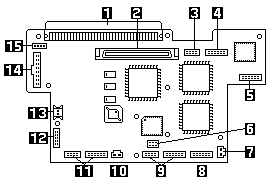
System Board

PS/2 CL57 SX system board with numbered callouts 1 to 15 for its connectors and components

  1. System Expansion Connector (150-pin)
  2. Display Control Card
  3. Serial Connector
  4. I/O Panel (Parallel/External Input)
  5. Indicator Card
  6. Password-Override Connector
  7. Backup Battery
  8. Communication Interface (Modem/Serial)
  9. Diskette Drive
  10. Thermal Sensor
  11. Hard Disk Drive
  12. Trackball/Keyboard Card Connector
  13. Dew Point Sensor
  14. Voltage Converter
  15. Voltage Converter

Power-On Password #

Source: Hardware Maintenance Manual Volume 1: Laptop, Notebook, Portable and ThinkPad Computers, p.144

Passwords

To service a computer with an active, unknown, power-on password, do the following.

  1. Power-off the computer and unplug the power cord.
  2. Remove the keyboard and top cover.
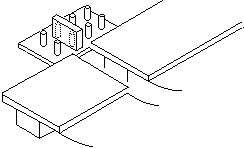
  3. Locate the override connector on the system board. Some models use connector J12 (8 pins shown below). Other models use connector J13 (a 2-pin connector).
  4. Install a jumper over the pins of the connector as shown.
  5. Power-on the computer to erase the password.
  6. After POST completes, remove the jumper. Otherwise, you will not be able to reset a power-on password.

Jumper installed on the 8-pin password-override connector (J12) on the system board, as used to erase the power-on password

To set the password, start the system programs, select Set features from the Main Menu, then select Set password and unattended start mode, and follow the instructions on the screen.

Restoring the Partition #

Source: Hardware Maintenance Manual Volume 1: Laptop, Notebook, Portable and ThinkPad Computers, p.145

If a computer or hard disk problem prevents system setup or diagnostic programs from being loaded from the protected partition, load and run the programs from the Reference Diskette. If no errors are found, restore the programs to the protected partition on the hard disk using the following procedure.

  1. Start the computer with the customer's backup copy of the Reference Diskette installed.
  2. Select the Backup/Restore system programs from the Main Menu.
  3. Select the Restore the system partition to load the system setup and utility programs, and the customer and advanced diagnostics programs onto the system partition of the hard disk.

If this does not correct the problem, use the backup copy of the Reference Diskette to format the hard disk and then restore the programs to the protected partition. If the problem remains, return to the I998XXXX, I9990303 error code (in the Symptom-to-FRU index).

Note: After the programs have been restored, the Diskette and F1 prompts appear, unless an operating system is present.

Parts Listing #

Source: Hardware Maintenance Manual Volume 1: Laptop, Notebook, Portable and ThinkPad Computers, p.153

Exploded view of the PS/2 CL57 SX with numbered callouts 1 to 28 matching the parts listing

System Unit

IndexPartFRU P/N
1Frame, Keyboard07G1393
2Bezel, LCD07G1391
3LCD Panel48G9999
4Cover, LCD Rear07G1392
Cable, LCD07G1384
5Speaker07G1229
6Indicator Card07G1375
Support, Indicator Card07G1398
7Top Cover07G1390
8Trackball Assembly1397752
9Guide, Modem07G1378
Bracket, Modem07G1408
10Hinge, Support07G1407
Hinge, Left07G1403
Hinge, Right07G1404
11Cover, I/O Connectors07G1394
12Cover, Option Slot07G1395
Cover, Math Coprocessor07G1429
13Backup Battery, Lithium35G2282
14Diskette Drive Assembly72X6074
Bracket, Diskette Drive07G1405
Cable, Diskette Drive07G1379
15Lid Switch07G1386
16Hard Disk Drive, 80MB95F4708
Bracket, Hard Disk Drive07G1406
Cable, Hard Disk Drive07G1380
17Bottom Cover07G1389
18Keyboard Control Card1397751
19Voltage Converter07G1373
202MB IC DRAM Card07G1414
4MB IC DRAM Card07G1415
8MB IC DRAM Card07G1416
21Regulator06G9536
22Connector, IC DRAM Card07G1377
23Memory Module Kit, System Board07G1879
24System Board07G1371
Note: On system board EC level C81806A, J2 and J12 have been removed, and the cable between J2 and Voltage Converter (index 19) is not used.
System Board Dew Sensor35G2319
25Switch, Communications Cartridge07G1385
26Display Control Card07G1372
27I/O Panel Assembly07G1374
Bracket, Connector (includes slide and connector screws)07G1402
Serial Connector Assembly07G1426
28Keyboard (see Keyboards)
Battery Pack, Rechargeable, HHR140A07G1413
For Benelux06G8433
For Nordic countries06G8434
For Switzerland06G8432
Battery Pack, Rechargeable, HHR150A06G9259
For Switzerland06G9264
Holder, Battery Pack07G1376
Sensor, Thermal07G1387
Slide, Brightness/Contrast07G1399
Slide, Power Switch07G1400
Slide, Volume Control07G1401
Foot, Left07G1396
Foot, Right07G1397
Cable, 50-Pin (voltage converter to system board)07G1382
Cable, 4-Pin (voltage converter to system board)07G1383
Communications Adapters:
Serial Adapter79F6840
Data/Fax Modem Adapter (U.S., Canada only)53G7772
High-Speed Data/Fax Modem (U.S., Canada only)92F0288
Telephone Cable94X1540
Miscellaneous Kit07G1409
Miscellaneous Kit, LCD07G1410
Screw Kit07G1411

Options and Adapters

PartFRU P/N
AC Adapter, CVCC, World Trade06G8457
for Japan06G8462
for U.S./Canada06G8452
AC Adapter, CT
for Japan35G2285
for U.S./Canada07G1412
Communications Cartridge07G3999
External Battery Pack34G9869
Battery Pack Cable (for 34G9869)34G9870
FaxConcentrator Adapter/A94X2540
FaxConcentrator Adapter/A Cable94X2527
Miniature Mouse95F5723
Strap07G1449
Trackball Cable07G1381

Keyboards

PartFRU P/N
French1397927
German1397926
Italian1397928
Japanese1398299
Spanish1397929
U.K. English1397925
U.S. English1397750
Cable, Keyboard07G1381

Numeric Keypad

PartFRU P/N
French95F6313
German95F6314
Italian95F6316
Spanish95F6315
U.K. English95F5741
U.S. English95F5741

Safety Notice 8 #

Warning Safety Notice 8

Before removing any FRU, power-off the computer, unplug all power cords from electrical outlets, remove the battery pack, then disconnect any interconnecting cables.

Avant de retirer une unité remplaçable en clientèle, mettez le système hors tension, débranchez tous les cordons d'alimentation des socles de prise de courant, retirez la batterie et déconnectez tous les cordons d'interface.

Die Stromzufuhr muß abgeschaltet, alle Stromkabel aus der Steckdose gezogen, der Akku entfernt und alle Verbindungskabel abgenommen sein, bevor eine FRU entfernt wird.

Prima di rimuovere qualsiasi FRU, spegnere il sistema, scollegare dalle prese elettriche tutti i cavi di alimentazione, rimuovere la batteria e poi scollegare i cavi di interconnessione.

Antes de quitar una FRU, apague el sistema, desenchufe todos los cables de las tomas de corriente eléctrica, quite la batería y, a continuación, desconecte cualquier cable de conexión entre dispositivos.

Safety Notice 1 #

Warning Safety Notice 1

Before the computer is powered-on after FRU replacement, make sure all screws, springs, or other small parts are in place and are not left loose inside the computer. Verify this by shaking the computer and listening for rattling sounds. Metallic parts or metal flakes can cause electrical shorts.

Avant de remettre l'ordinateur sous tension après remplacement d'une unité en clientèle, vérifiez que tous les ressorts, vis et autres pièces sont bien en place et bien fixées. Pour ce faire, secouez l'unité et assurez-vous qu'aucun bruit suspect ne se produit. Des pièces métalliques ou des copeaux de métal pourraient causer un court-circuit.

Bevor nach einem FRU-Austausch der Computer wieder angeschlossen wird, muß sichergestellt werden, daß keine Schrauben, Federn oder andere Kleinteile fehlen oder im Gehäuse vergessen wurden. Der Computer muß geschüttelt und auf Klappergeräusche geprüft werden. Metallteile oder -splitter können Kurzschlüsse erzeugen.

Prima di accendere l'elaboratore dopo che é stata effettuata la sostituzione di una FRU, accertarsi che tutte le viti, le molle e tutte le altri parti di piccole dimensioni siano nella corretta posizione e non siano sparse all'interno dell'elaboratore. Verificare ciò scuotendo l'elaboratore e prestando attenzione ad eventuali rumori; eventuali parti o pezzetti metallici possono provocare cortocircuiti pericolosi.

Antes de encender el sistema despues de sustituir una FRU, compruebe que todos los tornillos, muelles y demás piezas pequeñas se encuentran en su sitio y no se encuentran sueltas dentro del sistema. Compruébelo agitando el sistema y escuchando los posibles ruidos que provocarían. Las piezas metálicas pueden causar cortocircuitos eléctricos.